Plc-5 typed read - receive data message - slc plc – Comtrol UP DeviceMaster User Guide User Manual
Page 131
DeviceMaster UP EtherNet/IP User Guide: 2000424 Rev. L
Chapter 5. Programming the PLC - 131
PLC-5 Typed Read - Receive Data Message - SLC PLC
5.4.6.7. PLC-5 Typed Read - Receive Data Message - SLC PLC
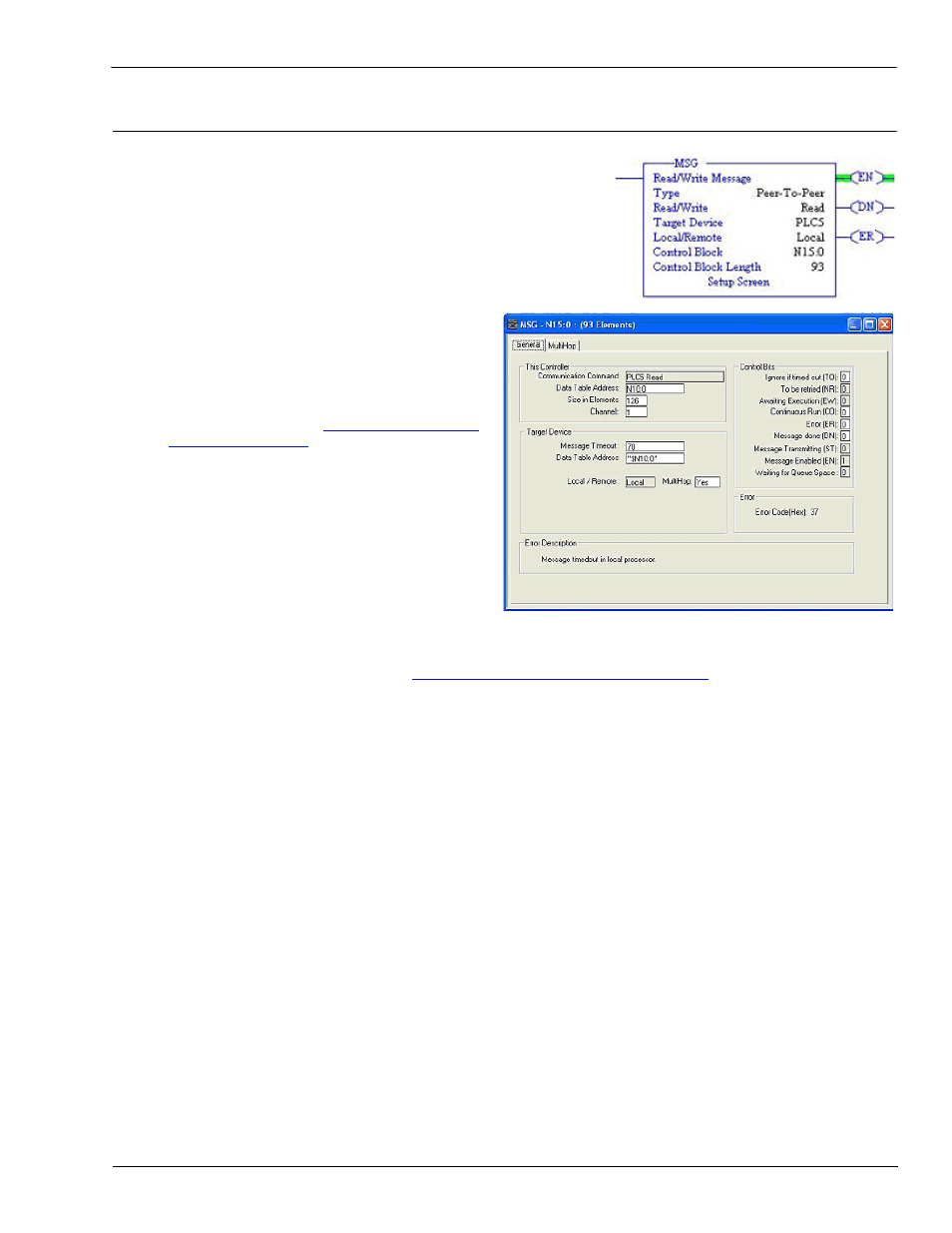
The following screen depicts a PLC-5 Typed Read - Receive Data
message in ladder logic.
Make the following changes to the ladder logic.
1.
Select the Read option.
2.
Select the PLC5 option.
3.
Select Local.
4.
Assign a dedicated integer file of 93 integers to the Control block.
In the ladder logic, double-click the Setup Screen in
the MSG instruction.
5.
Make the following changes.
a.
Specify the file address to receive data
information in the Data Table Address box on
This Controller panel. For more information
on file addresses, see
b.
Specify a size in the Size of Elements box that
is large enough to receive the entire data
message including the sequence number
and length fields.
c.
Set the Channel parameter to 1 to use the
Ethernet port.
The Message Timeout parameter is not
actually configurable. RSLogix 500 sets the
value in this box based on the Ethernet
timeout settings.
d.
Specify the port-specific receive file address for the DeviceMaster UP in the Data Table Address box on
the Target Device panel. The receive file address must be specified in logical ASCII format. For more
information on file addresses, see
2.4.2.1. DeviceMaster UP File Addressing
e.
Set the MultiHop option to Yes.