Comtrol UP DeviceMaster User Guide User Manual
Page 119
DeviceMaster UP EtherNet/IP User Guide: 2000424 Rev. L
Chapter 5. Programming the PLC - 119
Configure the DeviceMaster UP for the RSLogix 500 Example Program - SLC PLC
5.4.4. Configure the DeviceMaster UP for the RSLogix 500 Example Program -
SLC PLC
The following procedure configures the DeviceMaster UP for the RSLogix 500 example programs. You must
perform this task before you configure and run the RSLogix 500 example program. For more information on
the Server Configuration web pages, see
Chapter 3. Embedded Configuration Pages
1.
Attach a loopback plug to the serial port.
2.
Access the Server Configuration web page, using one of these methods.
•
Open PortVision DX, right-click the DeviceMaster UP for which you want to program network
information and click Webpage.
•
Open a browser and type the IP address for the DeviceMaster UP in the Address box.
3.
Click Port n. Where n is the port number.
4.
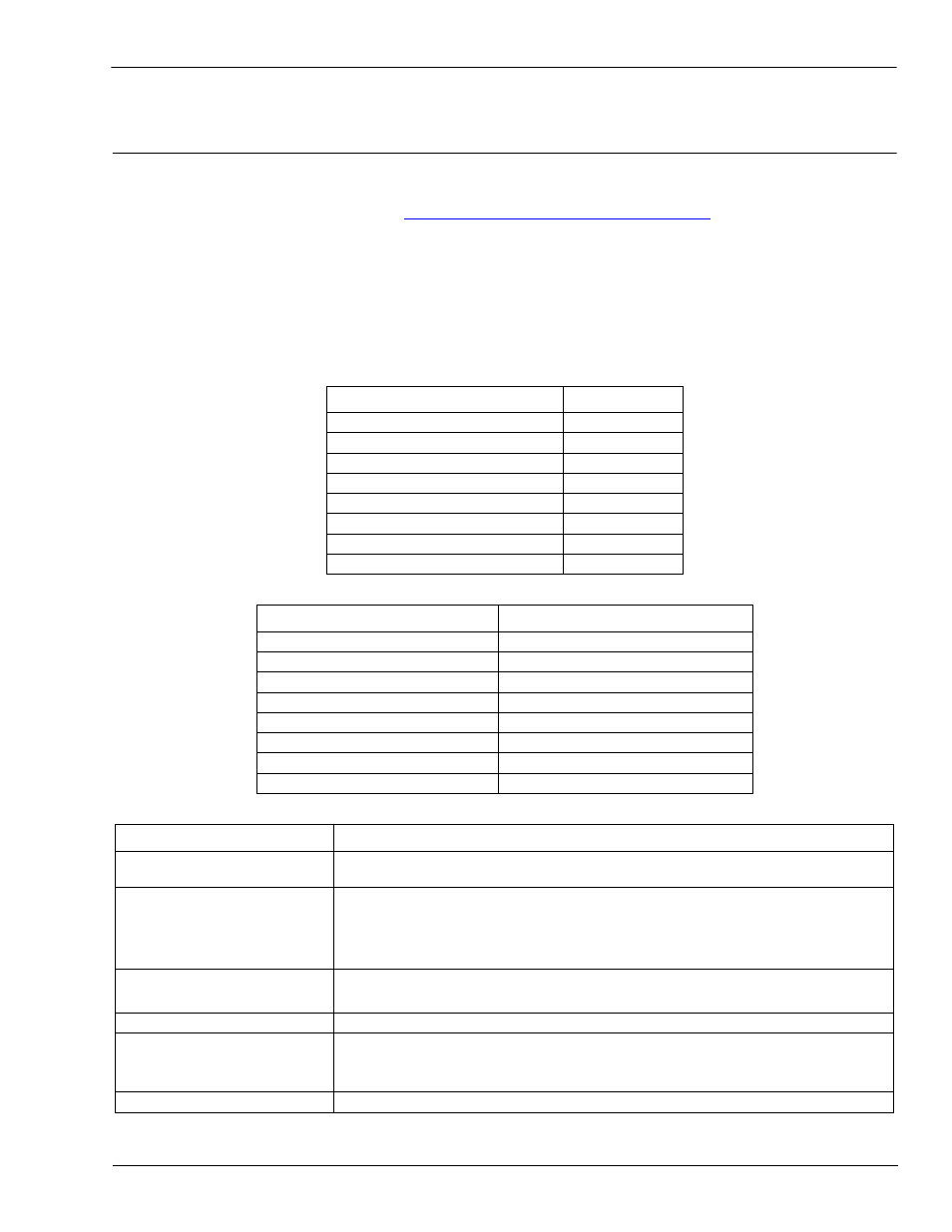
Set the serial port settings under Serial Configuration to the following values.
5.
Set the serial port settings under Serial Packet Identification to these values.
6.
Set the serial port settings under Ethernet/IP Settings to the following values:
Field
Setting
Mode
RS-232
Baud
57600
Parity
none
Data Bits
8
Stop Bits
1
Flow Control
none
DTR
off
Rx Timeout Between Packets
200
Field
Setting
STX RX Detect
Set to one byte and Byte 1 to 2.
ETX Rx Detect
Set to one byte and Byte 1 to 3.
STX Tx Append
Set to one byte and Byte 1 to 2.
ETX Tx Append
Set to one byte and Byte 1 to 3.
Strip Rx STX/ETX
Select
Discard Rx Packets With Errors Select
(PLC-5/SLC) Rx MS Byte First
Optionally, select
(PLC-5/SLC) Tx MS Byte First
Optionally, select
Field
Selection
TX Sequence Number
Checking
Select.
Rx (To PLC) Ethernet
Transfer Method
•
Set to
Polling for lpbkExampleSlcMsgPollRS500
and
lpbkExamplePlc5MsgPollRS500
.
•
Set to Write-to-Tag/File for lpbkExampleSlcMsgFileRS500.
•
Set to Write-to-Tag/File-Synced for lpbkExampleSlcMsgFileSyncRS500.
PLC IP Address
•
Leave blank for Polling.
•
Set to IP Address of PLC for Write-to-File and Write-to-File-Synced.
PLC Controller Slot Number Unused and can remain blank.
Rx (To PLC) Produced Data
Tag/File Name
•
Leave blank for Polling.
•
For SLC PLCs, set to $N10:0 and for MicroLogix PLCs, set to #N10:0; the
PLC receive filename for Write-to-File and Write-to-File-Synced.
Reset Port
Select.