1 flexible inspection loading – Banner PresencePLUS P4 COLOR Series User Manual
Page 42
5.4.1 Flexible Inspection Loading
Release 2009R1B introduces a more flexible inspection loading capability that allows most inspections created by any
PresencePLUS vision sensor to be loaded through the PresencePLUS software even if connected to a different type
of PresencePLUS vision sensor. This means that you can now load, for example, an inspection created by an OMNI
1.3 into PresencePLUS software connected to a standard OMNI. Prior to Release 2009R1B, inspections could only
be loaded into PresencePLUS software that was connected to the same type of PresencePLUS vision sensor that had
created the inspection. In other words, a ProII camera could only load inspections created by another ProII camera,
and an OMNI could only load an inspection saved from another OMNI, etc.
Note: The one limitation that still exists occurs when trying to load an inspection that uses a tool that is unavailable
(or unlicensed) for the currently connected sensor (for example, attempting to load to an inspection that uses a
Geometric Count tool to a PresencePLUS AREA sensor will not work because the Geometric Count tool is not
supported on the AREA sensor).
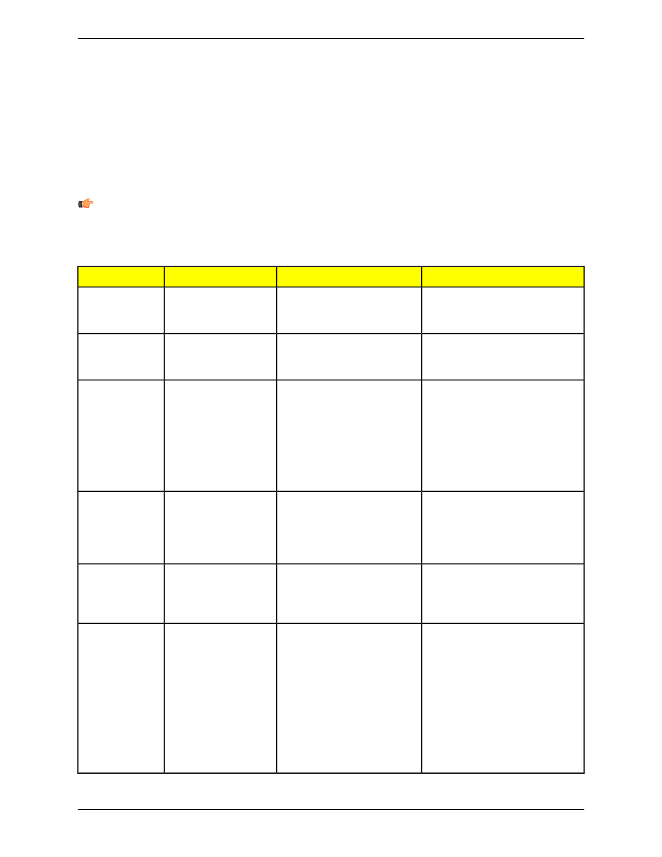
Possible Inspection Modifications
Result
Inspection Destination
Inspection Source
None required
A dialog indicates that the image
color has changed and the
inspection loads
Standard grayscale
sensor (for example, a
standard OMNI)
Color sensor (for
example, a Color
OMNI)
None required
A dialog indicates that the image
color has changed and the
inspection loads
Color sensor (for
example, a Color OMNI)
Grayscale sensor
(for example, a
standard OMNI)
Reposition image, adjust ROIs and
tools in the FOV, and possibly
acquire a new reference image
A dialog indicates that the
image/FOV has been adjusted
and the image loads the image
into the upper-left of the FOV.
Standard VGA sensor
(for example, a standard
AREA sensor)
High Resolution
(1.3) sensor (for
example, an
AREA 1.3 sensor
)
Note that the image may be
cropped at the right and/or
bottom and ROIs may be outside
the image area
Possibly acquire a new reference
image
A dialog indicates that the FOV
has been adjusted and the
inspection loads with the image
centered in the FOV
High Resolution (1.3)
sensor (for example, an
AREA 1.3 sensor)
Standard VGA
sensor (for
example, a
standard AREA
sensor)
Adjust I/O as appropriate
A dialog indicates that the
inspection uses I/Os not
Sensor with 4 I/O (for
example, an OMNI)
Sensor with 6 I/O
(for example, a
ProII)
available on the sensor and the
inspection loads
Retest and modify timings as
appropriate, and possibly acquire a
new reference image
A dialog indicates that the timing
was adjusted and the inspection
loads with the timing(s) adjusted
to the maximum time allowed on
that sensor
Sensor that supports a
smaller maximum trigger
delay, trigger width,
NTSC fail/hold time, or
exposure time (for
example, a standard
Sensor that
supports a larger
maximum trigger
delay, trigger
width, NTSC
fail/hold time, or
OMNI maximum trigger
delay set to 8000 ms)
exposure time (for
example, a ProII
maximum trigger
delay set to 10000
ms)
Banner Engineering Corp.
Minneapolis, MN USA
42
2/2010
Tools Screen