3 p4 cable connections – Banner PresencePLUS P4 COLOR Series User Manual
Page 11
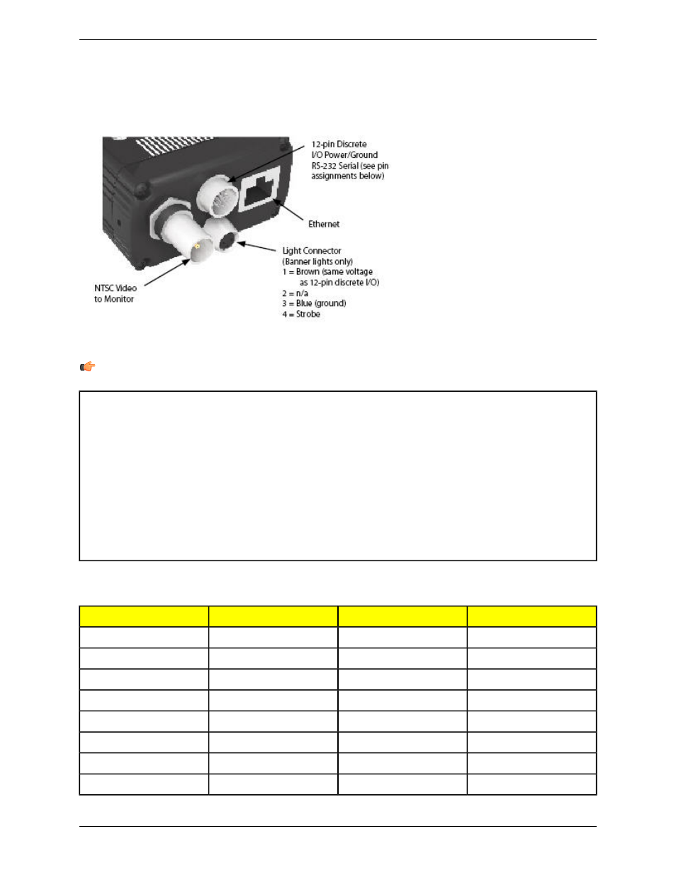
2.1.3 P4 Cable Connections
Note: The sensor power must be 24V dc ± 10% if a light source is powered by the sensor.
Monitor Cable (to Video Monitor, optional)
Crossover Ethernet Cable (to PC Ethernet Port)*
BNC06 —2 m (6')
STPX07 — 2.1 m (7')
BNC15 — 5 m (15')
STPX25 — 7.6 m (25')
BNC30 — 9 m (30')
or
Serial Cable (to PC serial Port)*
Standard Ethernet Cable (to PC via Network Hub or
Switch
DB9P06 — 2 m (6')
STP07 — 2.1 m (7')
DB9P15 — 5 m (15')
STP25 — 7.6 m (25')
DB9P30 — 9 m (30')
*The Sensor can be connected to the PC via a serial cable or an Ethernet network; Ethernet provides faster
communication.
Direction
Description
Wire Color
Pin #
Output
RS-232 TX**
Yellow
1
Input
Remote Teach
Gray
2
Input
Product Change
Orange
3
Input
External Trigger
Pink
4
In/Out
Discrete I/O #1
Black
5
In/Out
Discrete I/O #2
Red
6
In/Out
Discrete I/O #3
White
7
In/Out
Discrete I/O #4
Light Blue
8
11
Minneapolis, MN USA
Banner Engineering Corp.
System Description
2/2010