Feedback specifications explained, Motor and auxiliary feedback specifications – Rockwell Automation 2093-xxxx Kinetix 2000 Multi-axis Servo Drive User Manual User Manual
Page 57
Publication 2093-UM001A-EN-P — March 2007
Kinetix 2000 Connector Data
57
Feedback Specifications
Explained
The integrated axis module (IAM) and axis module (AM) can accept motor
and auxiliary feedback signals from the following types of encoders:
• Stegmann Hiperface (SKS, SKM, SRS, SRM)
• Tamagawa 17 bit absolute encoders (TL5669)
• Sine/Cosine w/Marker (0.6
...
1.2V p-p) w/ single-ended hall
Commutation Tracks
• Sine/Cosine w/Marker (0.6
...
1.2V p-p)
• Differential TTL line driver (RS422) with Marker and single-ended Hall
Commutation Tracks
• Differential TTL line driver (RS422) with Marker
• Differential TTL line driver or Sine/Cosine with Hall Effect
Commutation and E-Travel inputs from Anorad Raptor linear motors.
Renishaw linear encoders are provided on this product.
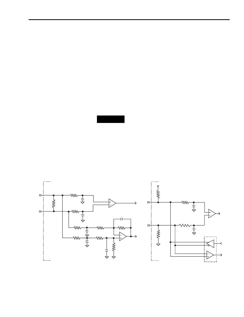
Motor and Auxiliary Feedback Specifications
AM, BM, and IM input encoder signals are filtered using analog and digital
filtering. The inputs also include illegal state change detection.
AM, BM, and IM Motor Encoder Input Circuits
TIP
Auto-configuration in RSLogix 5000 software of intelligent
absolute, high-resolution, and incremental encoders is possible
only with Allen-Bradley motors.
10 k
Ω
10 k
Ω
+5 V
1 k
Ω
1 k
Ω
+
-
56 pF
56 pF
10 k
Ω
1 k
Ω
1 k
Ω
10 k
Ω
1 k
Ω
1 k
Ω
1 k
Ω
1 k
Ω
1 k
Ω
100 pF
+
-
100 pF
56 pF
56 pF
56 pF
56 pF
Drive
Drive
AM and BM Channel Inputs
IM Channel Input