Controlling a brake example, Controlling a brake example on, Important – Rockwell Automation 2093-xxxx Kinetix 2000 Multi-axis Servo Drive User Manual User Manual
Page 181
Publication 2093-UM001A-EN-P — March 2007
Interconnect Diagrams
181
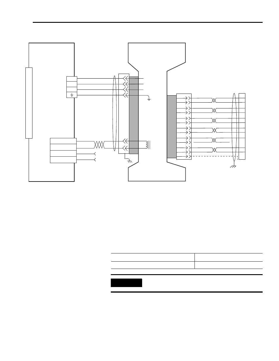
AM (230V) Wiring Example with Y-Series Motor
Controlling a Brake Example
The relay output of the Kinetix 2000 drive MBRK± signals (BC-2 and BC-3) is
suitable for directly controlling a motor brake, subject to the relay voltage limit
of 30V dc, and the relay current limit as shown in the table below.
Brake Relay Current Limit
1
2
3
4
BR-
BR+
9
7
U
V
W
0
1
2
3
4
5
6
7
8
9
10
11
12
13
14
15
U
V
W
AM+
AM-
BM+
BM-
IM+
IM-
S1
S2
GREEN
WHT/GREEN
BLACK
WHT/BLACK
RED
WHT/RED
1
2
3
4
14
6
5
10
GRAY
WHT/GRAY
12
13
8
S3
–
BROWN
WHT/BROWN
WHT/BLUE
BLUE
22
23
24
9
10
11
12
13
14
15
17
19
–
+5VDC
ECOM
DRAIN
1
2
3
4
GND
3/Black
2/Black
1/Black
Green/Yellow
Black
Black
2
3
1
4
Y-Series (230V)
SERVO MOTOR WITH
INCREMENTAL FEEDBACK
Three-Phase
Motor Power
Brake
Motor
Feedback
Motor Feedback
(MF) Connector
(IAM/AM)
2090-XXNFY-S
xx
Feedback Cable
Note 4, 9
Pigtail
Refer to Low Profile Connector
illustration (below)
for proper grounding technique.
KINETIX 2000
IAM (inverter) or AM
Note 8
Motor Power
(MP)
Connector
BRK +
BRK -
PWR
COM
24V dc
(1.2A max.)
User Supplied
Motor Feedback
(MF)
Connector
Motor
Brake
(BC)
Connector
Pigtail
Kinetix 2000 IAM/AM
Brake Current Rating, Max
2093-AC05-Mxx, 2093-AMPx, 2093-AM0x 1.0A
IMPORTANT
For brake requirements outside of these limits, an external relay must
be used.