Important – Rockwell Automation 2093-xxxx Kinetix 2000 Multi-axis Servo Drive User Manual User Manual
Page 100
Publication 2093-UM001A-EN-P — January 2007
100
Connecting the Kinetix 2000 Drive System
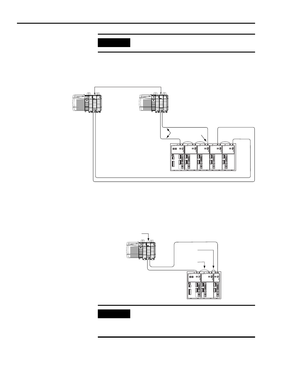
In this example, two Logix modules are installed in separate Logix chassis.
Fiber-optic Cable Example 2 (two Logix chassis)
When connecting a 2093-AC05-MPx integrated axis module or 2093-AM0x
(double-wide) axis modules, use 2090-SCEP0-2, 0.2 m (7.0 in.) cables. When
connecting 2093-AMPx, (single-wide) axis modules, use 2090-SCEP0-1, 0.1 m
(5.1 in.) cables.
Fiber-optic Cable Example 3 (Double-wide Modules)
IMPORTANT
The CompactLogix platform (1768-M04SE) is limited to four axes per
module.
SERCOS interface
TM
Tx (rear)
Rx (front)
OK
CP
SERCOS interface
TM
Tx (rear)
Rx (front)
OK
CP
1756-M08SE SERCOS Interface Modules
Logix Chassis
(ControlLogix is shown)
Transmit
Receive
Receive
Transmit
Transmit
Receive
Transmit
Receive
SERCOS Fiber-Optic Ring
SERCOS Fiber-Optic Ring
Kinetix 2000 System
(2093-PRS8S power rail)
SERCOS in t erface
TM
Tx (rear)
Rx (front)
OK
CP
0.1 m
(5.1 in.)
0.2 m
(7.0 in.)
Kinetix 2000 System
(2093-PRS4 power rail)
ControlLogix Chassis
1756-M08SE SERCOS
Interface Module
SERCOS Fiber-Optic Ring
IMPORTANT
Clean the fiber-optic cable connectors prior to installation. Dust in the
connectors can reduce signal strength.
For more information, refer to Fiber-optic Cable Installation and
Handling Instructions, publication 2090-IN010.