Step 5 – Rockwell Automation 2093-xxxx Kinetix 2000 Multi-axis Servo Drive User Manual User Manual
Page 124
Publication 2093-UM001A-EN-P — March 2007
124
Configure and Startup the Kinetix 2000 Drive System
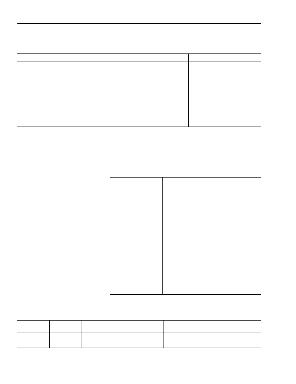
The Fault Status LED indicator initially flash the SERCOS node address,
then cycles through phases until final configuration (phase 4) is reached.
For additional troubleshooting information, refer to the appropriate
SERCOS Installation Instructions referenced on page 10.
5. Determine your source of three-phase input power.
6. Observe the Drive, Comm, and Bus status LED indicators on the front
of the IAM/AM.
IAM/AM Fault Status LED Indicator
Status
Do This
Actively cycling (phase 0)
The drive is looking for a closed SERCOS ring. Wait for
phase 1 or take corrective action until you reach phase 1.
Check fiber-optic connections.
Displaying a fixed 1 (phase 1)
The drive is looking for active nodes. Wait for phase 2 or
take corrective action until you reach phase 2.
Check node addressing.
Displaying a fixed 2 (phase 2)
The drive is configuring nodes for communication. Wait for
phase 3 or take corrective action until you reach phase 3.
Check program motor and drive
configuration against installed hardware.
Displaying a fixed 3 (phase 3)
The drive is configuring device specific parameters. Wait for
phase 4 or take corrective action until you reach phase 4.
Check motor catalog number against
selection.
(1)
Displaying a fixed 4 (phase 4)
The drive is configured and active.
Go to Step 6.
Flashing an E followed by two numbers
Drive is faulted.
Refer to Error Codes on page 134.
(1)
You can get diagnostic information from the module by highlighting the module name in RSLogix 5000 software. A Pseudo Key Failure often indicates that the motor
selection does not match the installed motor.
If your three-phase power
Then
Is sourced from a LIM
a. Set CB1 to the ON position.
b. Verify the Hardware Enable Input signal
(IOD/AF pin 43) for each axis is at 0 volts.
c. Remove the connection between IOD/AF
pins 43 and 44 if one exists.
d. Go to main step 4.
Is not sourced from a LIM
a. Apply 170...264V (230V) ac input power to
the IAM (IPD connector).
b. Verify the Hardware Enable Input signal
(IOD/AF pin 43) for each axis is at 0 volts.
Remove the connection between IOD/AF
pins 43 and 44 if one exists.
c. Go to main step 4.
Status LED
Indicator
Condition
Status
Do This
Drive
Off
Normal condition
Observe the Comm Status LED indicator.
Steady red
Drive is faulted
Refer to IAM/AM Status Indicators on page 139.