Rockwell Automation 2093-xxxx Kinetix 2000 Multi-axis Servo Drive User Manual User Manual
Page 30
Publication 2093-UM001A-EN-P — March 2007
30
Planning the Kinetix 2000 Drive System Installation
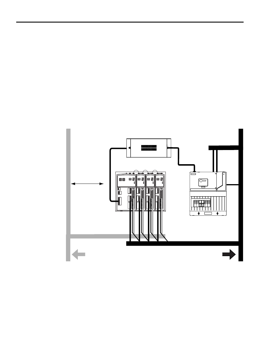
Observe the following guidelines when a LIM (2094-ALxxS, or
2094-XL75S-Cx) is used in the Kinetix 2000 system and mounted left of the
IAM with the ac (EMC) line filter mounted above the LIM:
• The clean zone (C) is to the left and below the Kinetix 2000 system
(grey wireway).
• The dirty zone (D) is to the right and above the Kinetix 2000 system,
and above and below the LIM (black wireway).
• The very dirty zone (VD) is from the filter output to IAM. Shielded
cable is required on the EMC filter (load side) and the braided shield
attached to the clamp provided.
• The SERCOS fiber-optic cables are immune to electrical noise.
Establishing Noise Zones (LIM mounted right of IAM)
(1)
If IAM/AM I/O cable contains (dirty) relay wires, route cable with LIM I/O cable in dirty wireway.
(2)
When space does not permit the 150 mm (6.0 in.) segregation, use a grounded steel shield instead. For
examples, refer to Chapter 4 of the System Design for Control of Electrical Noise Reference Manual,
publication GMC-RM001.
C
VD
D
D
D
C
VD
D
D
D
Very Dirty Filter/IAM Connections
Segregated (Not in Wireway)
Fiber-optic Cable
Clean Wireway
Dirty Wireway
Line Interface Module
Kinetix 2000
Drives
Route Motor Power and
24V dc I/O Shielded Cables
Route Encoder/Analog/Registration
Shielded Cables
V ac Line
V ac LOAD
Line Filter
I/O and Feedback Cables
(1)
No Sensitive
Equipment
Within 150 mm
(2)
MAIN VAC