Rockwell Automation 2093-xxxx Kinetix 2000 Multi-axis Servo Drive User Manual User Manual
Page 173
Publication 2093-UM001A-EN-P — March 2007
Interconnect Diagrams
173
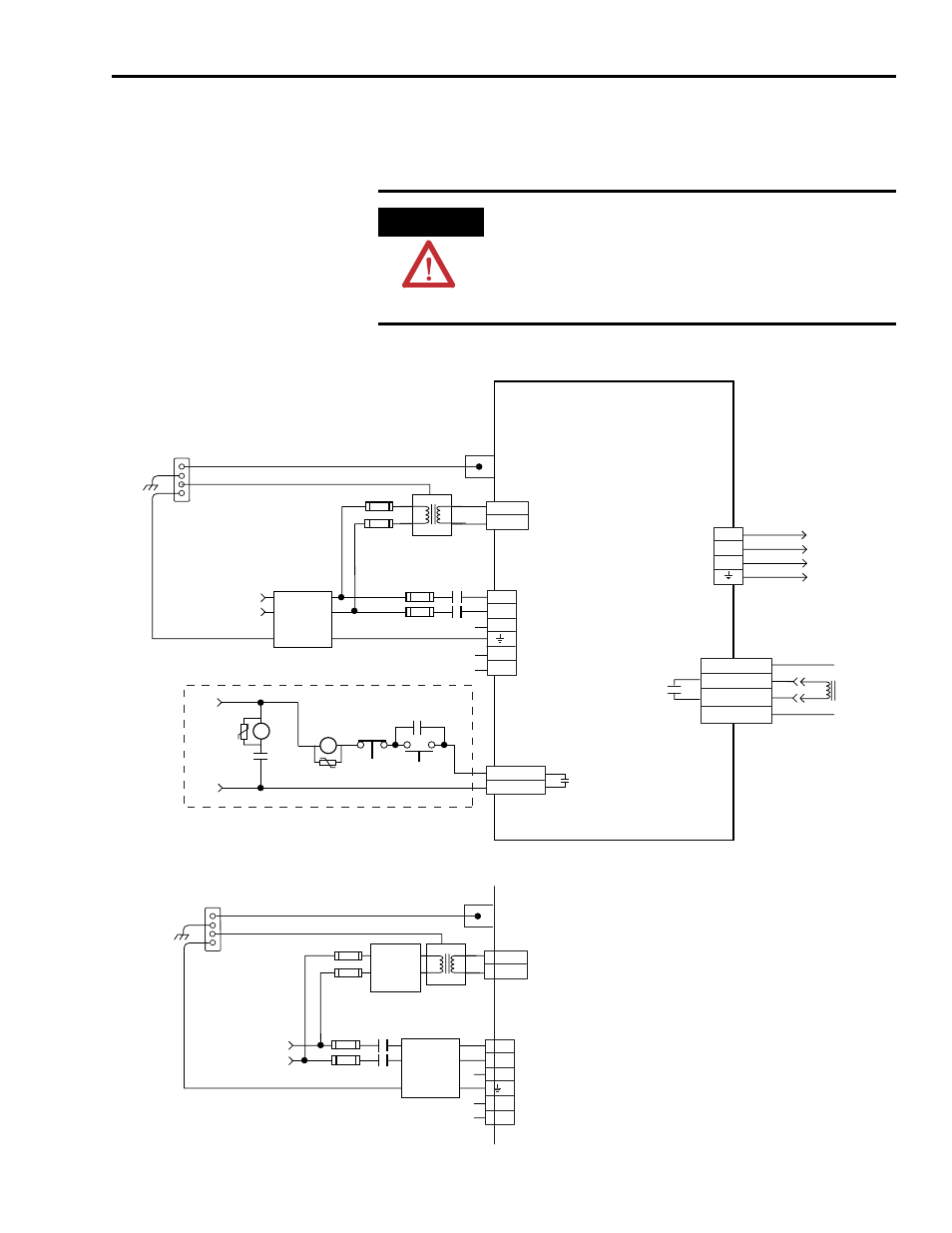
The configuration on this page does not include a LIM. You must supply input
power components. The single-phase and three-phase line filters are wired
downstream of fusing and the M1 contactor.
Single-Phase Power Input (without LIM) to IAM Wiring Example
ATTENTION
Wiring the contactor enable (CED) relay is required. To avoid
injury or damage to the drive, wire the contactor enable relay
into your safety control string.
Refer to Contactor Enable Relay on page 53, for more
information.
L1
L2
L3
DC+
DC-
CTRL 1
CTRL 2
CONT_EN+
CONT_EN-
U
V
W
1
2
3
4
1
2
3
4
5
6
1
2
1
2
1
2
3
4
PWR
MBRK+
MBRK-
COM
BR+
BR-
CTRL_1
CTRL_2
1
2
3
4
5
6
1
2
L1
L2
L3
DC+
DC-
Input
Fusing *
24V AC/DC
or
120V AC,
50/60 HZ
Single-Phase Input
170-264V ac RMS
Notes 1, 2
START *
* INDICATES USER -SUPPLIED COMPONENT
Control Power
(CPD) Connector
CR1*
M1 *
CR1 *
CR1 *
STOP *
Input
Fusing *
Notes 2, 12
Contactor Enable
(CED) Connector
KINETIX 2000
INTEGRATED AXIS MODULE
2093-AC05-MP
x
Three-Phase
Motor Power
Connections
Note 14
Main Power
(IPD) Connections
M1 * Notes 8, 19, 20
Refer to Attention statement (Note 11)
Motor Power
(MP) Connector
Single-Phase
AC Line Filter
Note 3
Bonded Cabinet Ground Bus *
Power Rail
Ground Stud
VAC Line
Single-Phase Input
170-264V ac RMS
Notes 1, 2
Isolation
Transformer *
Note 5
Chassis
I/O Connection
I/O Connection
Motor Brake
Connections
Motor Brake
(BC) Connector
Single-Phase
AC Line Filter
Note 3
Bonded Cabinet Ground Bus *
Power Rail
Ground Stud
Input
Fusing *
M1 *
Notes 8, 19, 20
VAC Line
Single-Phase Input
170-264V ac RMS
Note 1, 2
Isolation
Transformer *
Note 5
Chassis
Single-Phase Input
170-264V ac RMS
Notes 1, 2
Control Power
(CPD) Connector
Main Power
IIPD) Connections
Input
Fusing *
Single-Phase
AC Line Filter
Note 3
ALTERNATE INPUT POWER CONNECTION SCHEME