Motor brake relay – Rockwell Automation 2093-xxxx Kinetix 2000 Multi-axis Servo Drive User Manual User Manual
Page 54
Publication 2093-UM001A-EN-P — March 2007
54
Kinetix 2000 Connector Data
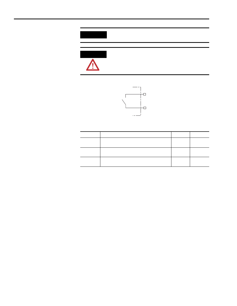
Contactor Enable Relay Circuit
Contactor Enable Relay Output Specifications
Motor Brake Relay
Two connections are required for the (customer-supplied) motor brake input
power (BC-1 and BC-2) and two connections each for the motor brake output,
as shown in the figure below. Connections are rated for +24V and current as
shown in the table below.
An active signal releases the motor brake (BC-2 and BC-3). The brake signal
on each inverter contains a suppression device. The brake turn-on delay
specified in RSLogix 5000 software delays application of the motor brake
activation by the time interval specified, and the brake turn-off delays release
of the motor brake by the time interval specified for the signal.
Refer to Axis Module/Motor Wiring Examples beginning on page 178 and
Controlling a Brake Example on page 181 for wiring examples.
IMPORTANT
All power rail slots must have the proper module installed or the
Contactor Enable relay will not close.
ATTENTION
To avoid damage to the drive, wire the Contactor Enable relay in your
safety control string so that three-phase power is removed from the
drive in the event of certain fault conditions.
Refer to Power Wiring Examples on page 169 for wiring examples.
CONT EN-
CONT EN+
Normally
Open
Relay
Kinetix 2000 IAM
Parameter
Description
Min
Max
On-state
current
Current flow when the relay is closed
—
1 A
On-state
resistance
Contact resistance when the relay is closed
—
1
Ω
Off-state
voltage
Voltage across the contacts when the relay is open
—
120V ac or
24V dc