Node addressing example 4 on, 108 fo – Rockwell Automation 2093-xxxx Kinetix 2000 Multi-axis Servo Drive User Manual User Manual
Page 108
Publication 2093-UM001A-EN-P — March 2007
108
Configure and Startup the Kinetix 2000 Drive System
Node Addressing Example 4
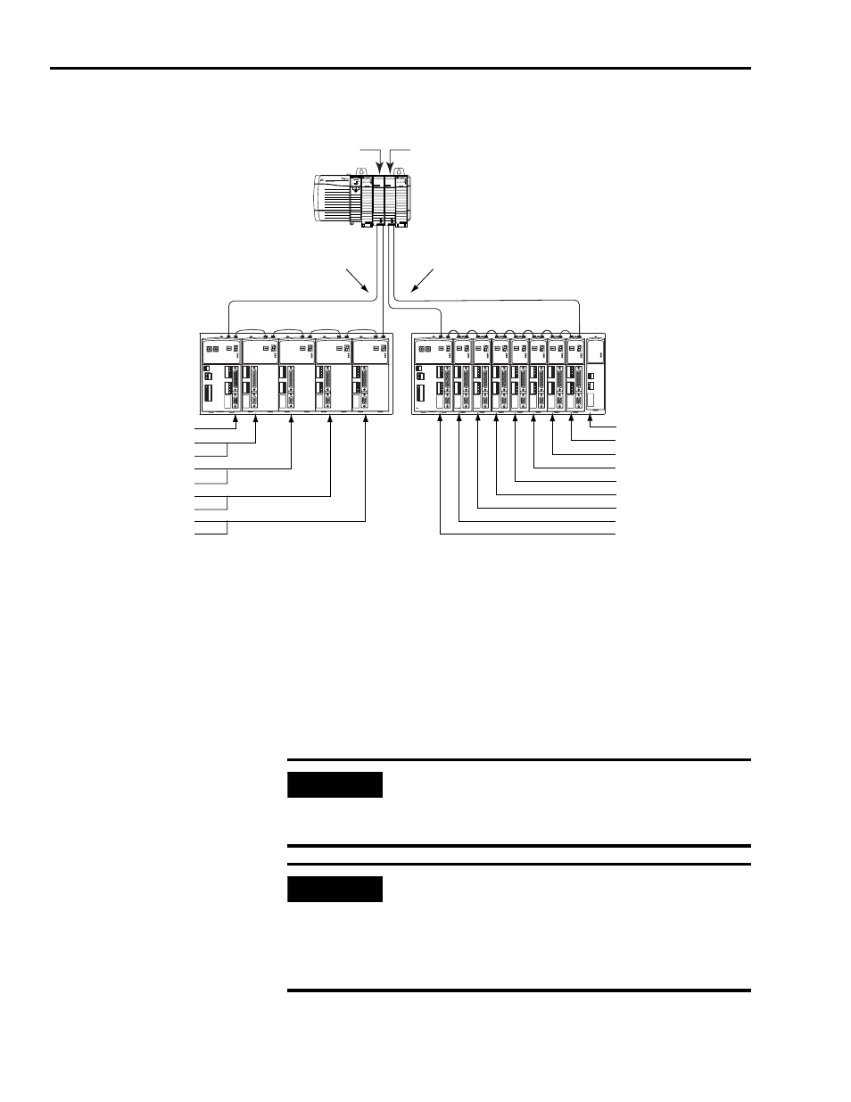
In Example 4, xxxxx system 1 with an eight-axis power rail contains one IAM,
and four double-wide AMs. xxxxx system 2 with an eight-axis power rail
contains one IAM, eight single-wide AMs, and a shunt module.
SERCOS interface module 1 controls axes 1...5, and module 2 controls axes
9...16.
The shunt module (or a slot filler) in xxxxx system 2 occupies a slot, but is not
assigned a node address, since future expansion of this system is impossible.
SERCOS interface
TM
Tx (rear)
Rx (front)
OK
CP
SERCOS interface
TM
Tx (rear)
Rx (front)
OK
CP
ControlLogix Chassis
1756-M08SE SERCOS
Interface Module 2
SERCOS Fiber-optic Ring
Receive
Transmit
Receive
Kinetix 2000
System 1
(2093-PRS8S power rail)
1756-M08SE SERCOS
Interface Module 1
Transmit
Kinetix 2000
System 2
(2093-PRS8S power rail)
Node Addresses:
N/A*= Shunt (not an axis)
17 = axis 16 (single-wide AM)
16 = axis 15 (single-wide AM)
15 = axis 14 (single-wide AM)
14 = axis 13 (single-wide AM)
13 = axis 12(single-wide AM)
12 = axis 11 (single-wide AM)
11 = axis 10 (single-wide AM)
10 = axis 9 (IAM) base node address
* Unavailable for axis use in a
2093-PRS8S power rail occupied
by eight single-wide AMs.
Node Addresses:
01 = axis 1 (IAM) base node address
02 = axis 2 (single-wide AM)
03** = NA (axis 2 occupies slot)
04 = axis 3 (double-wide AM)
05** = NA (axis 3 occupies slot)
06 = axis 4 (double-wide AM)
07** = NA (axis 4 occupies slot)
08 = axis 5 (double-wide AM)
09** = NA (axis 5 occupies slot)
** Occupied, but not in use, by
2093-PRS8S power rail occupied
by four double-wide AMs.
SERCOS Fiber-optic Ring
IMPORTANT
Only the following modules may occupy slot eight in the 2093-PRS8S
power rail: a shunt module (2093-ASP06), a slot filler (2093-PRF), or a
double-width axis module (2093-AM01 or 2093-AM02) occupying
both slots seven and eight.
IMPORTANT
The node address for each axis module is determined by the base
node-address switch setting on the IAM.
Do not position axis modules to the right of a shunt or slot filler
modules. The added distance between non-adjacent axes can
increase electrical noise and impedance, and requires longer
fiber-optic cable lengths.