Rockwell Automation 2093-xxxx Kinetix 2000 Multi-axis Servo Drive User Manual User Manual
Page 180
Publication 2093-UM001A-EN-P — March 2007
180
Interconnect Diagrams
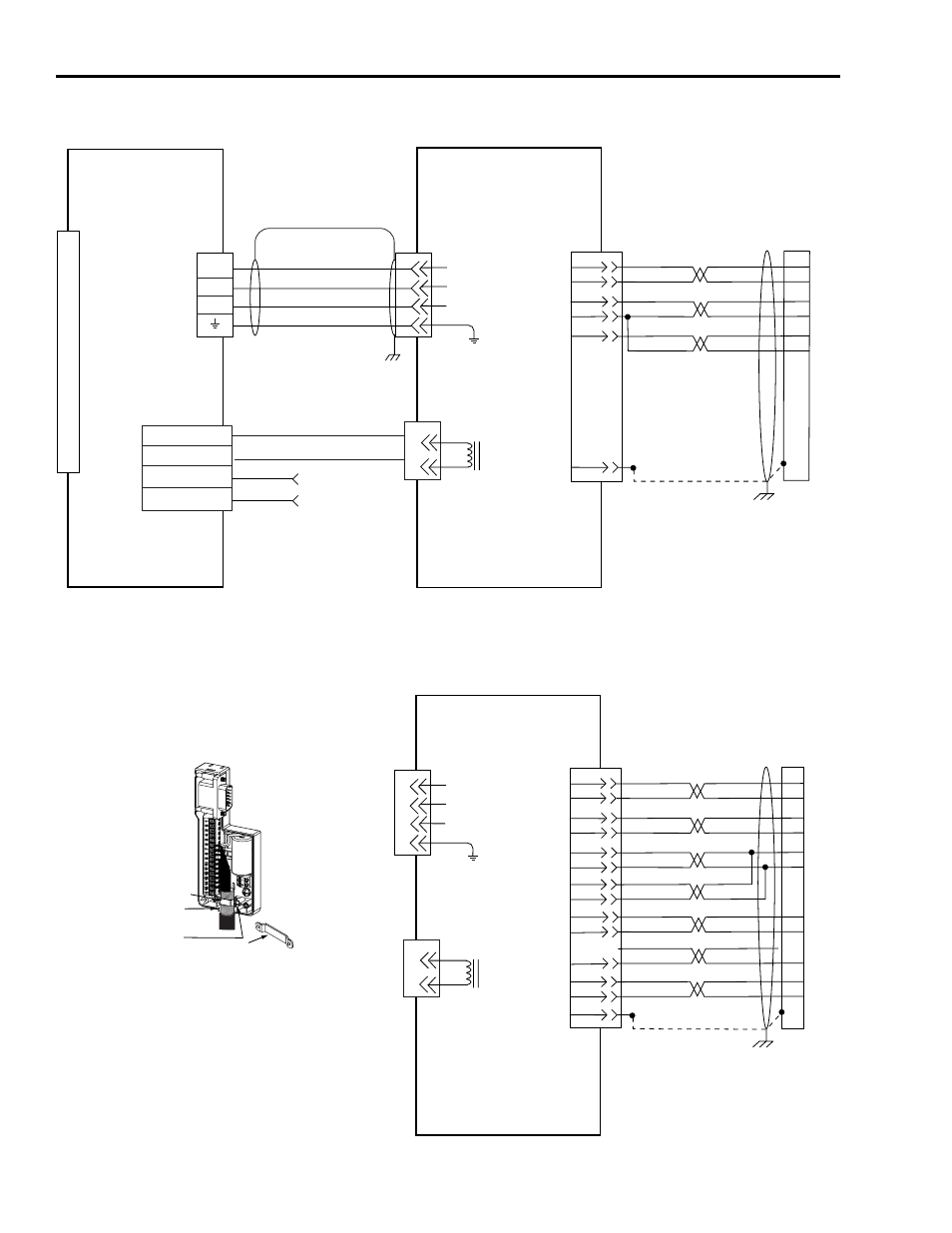
Wiring Example for TL-Series Motor with 230V Axis Module (IAM or AM)
BR+
BR-
1
2
SD+
SD-
+5VDC
ECOM
BAT+
BAT-
ORANGE
WHT/ORANGE
BROWN
WHT/BROWN
GRAY
WHT/GRAY
5
10
14
6
BAT+
BAT-
12
13
7
8
14
0
1
2
3
4
5
6
7
8
9
10
11
12
13
14
15
Black
White
9
2
3
1
4
MBRK +
MBRK -
PWR
COM
24V dc
(1.2A max.)
User Supplied
1
2
3
4
U
V
W
1
2
3
4
Brown
Black
Blue
Green/Yellow
GND
U
V
W
AM+
AM-
BM+
BM-
IM+
IM-
+5VDC
ECOM
BLUE
WHT/BLUE
GREEN
WHT/GREEN
GRAY
WHT/GRAY
BLACK
WHT/BLACK
RED
WHT/RED
7
8
1
2
3
4
5
10
14
6
12
6
S1
9
S2
S3
YELLOW
WHT/YELLOW
11
15
13
8
1
2
3
4
5
10
1
2
BR+
BR-
1
2
4
3
2
1
1
2
3
4
U
V
W
GND
12
13
SD+
SD-
Three-Phase
Motor Power
Motor Feedback
(MF)
Connector
(IAM or AM)
Motor Feedback
Brake
TL-Series (230V)
SERVO MOTOR
WITH
HIGH RESOLUTION
FEEDBACK
2090-DANBT-18S
xx Brake Cable
Note 4
2090-XXNPT-
xx Sxx Motor
Power Cable
Note 4
KINETIX 2000
IAM (inverter) or AM
Note 8
Motor Power
(MP)
Connector
Motor Feedback
(MF)
Connector
2090-XXNFLT-Sxx
Feedback Cable
Notes 4, 9
Exposed shield
secured under clamp
Clamp
Turn clamp over to hold
small cables secure
Clamp screw
Low Profile
Connector
(2090-K2CK-D15M
shown)
Grounding Technique for
Feedback Cable Shield
Motor
Brake
(BC)
Connector
2090-XXNFT-S
xx or
2090-XXNFLT-Sxx (shown)
Feedback Cable
Notes 4, 9
Motor Feedback
(MF)
Connector
(IAM/AM)
TL-Series (230V)
SERVO MOTOR
WITH
INCREMENTAL FEEDBACK
Three-Phase
Motor Power
Motor Feedback
Brake
DRAIN
DRAIN
Refer to Low Profile Connector
Illustration (lower-left)
for proper grounding technique
Refer to Low Profile Connector
Illustration (lower-left)
for proper grounding technique