Single axis rs-232 set up, Rs-232 connection diagrams, Address 0 – Rockwell Automation 1398-DDM-xxx ULTRA 100 Series Drives Installation Manual User Manual
Page 98: 9600 baud
Publication 1398-5.2 – PDF 1997
6-34
Interfaces
Single Axis RS-232 Set Up
A single ULTRA 100 Series drive may be selected using RS-232
communications. After cabling is attached to the unit and the drive
address is assigned, configuration of (i.e., communications with) the
unit may proceed.
Factory default settings for a ULTRA 100 Series drive are:
●
Address 0
●
9600 Baud
●
8 Data, No Parity, 1 Stop bit
The following steps outline how to select the communications options:
1. Connect an RS-232 cable between the computer and a serial con-
nector on the drive (J5).
2. Verify the computer can communicate with the drive by perform-
ing the following:
A. Switch drive power to ON
B. Start ULTRA Master on the attached PC
C. Choose
CANCEL
from the Drive Select window
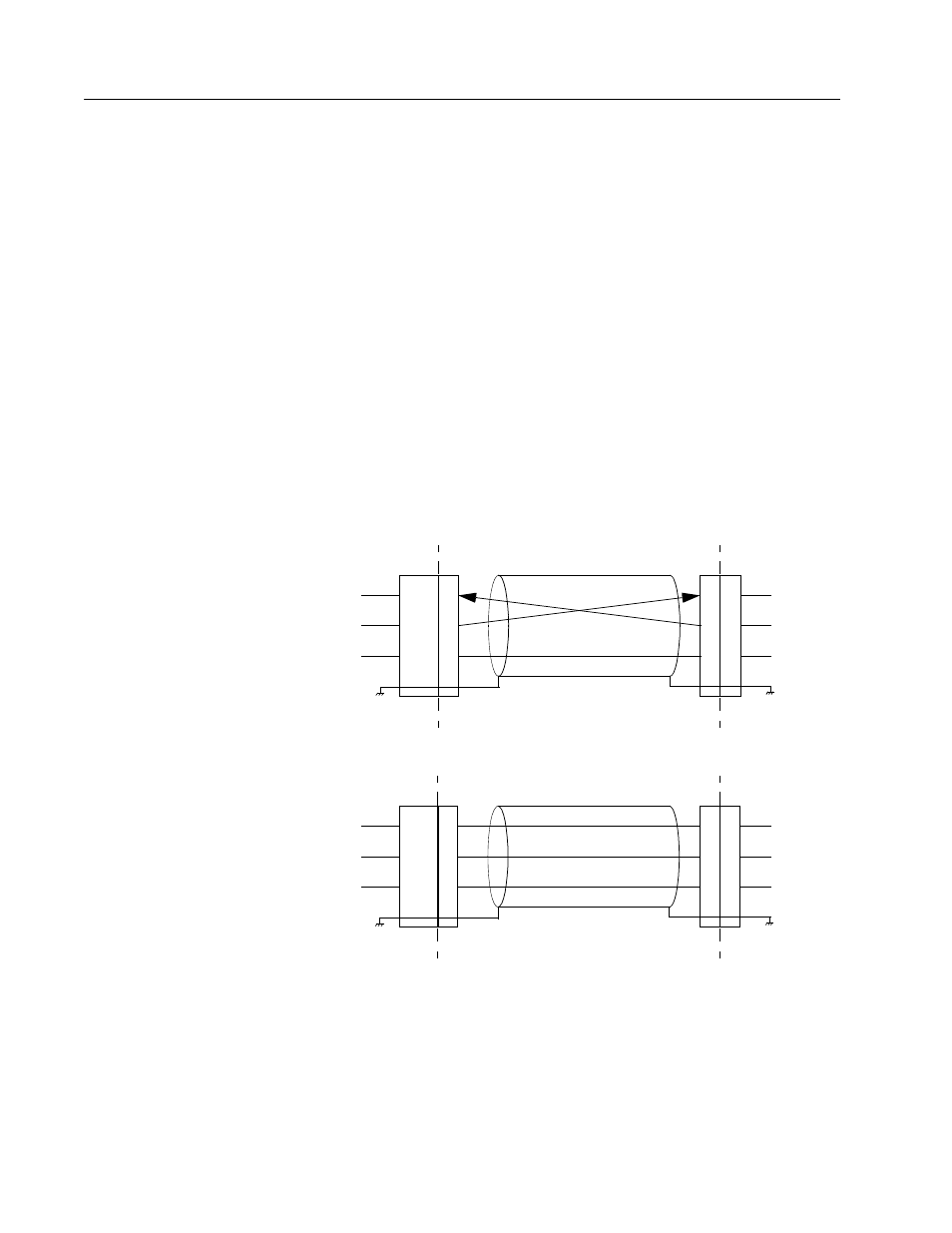
Figure 6.40
RS-232 Connection Diagrams
USER
2
9-Pin
Drive
2
Drive Chassis
PC
3
3
5
Male
RS-232 CABLE
J5
2
3
5
RCV
XMT
COM
RCV*
XMT*
COM*
* PC pin-outs
may vary by
manufacturer
9-Pin
Female
9-Pin Male Connector to 9-Pin Female Connector
9-Pin
RS-232
USER
2
9-Pin
Drive
2
Drive Chassis
PC
3
3
5
7
Male
RS-232 CABLE
J5
2
3
5
RCV
XMT
COM
XMT*
RCV*
COM*
25-Pin
Female
9-Pin Male Connector to 25-Pin Female Connector
25-Pin
RS-232
5
* PC pin-outs
may vary by
manufacturer