J5 – serial port, Ultra 100 series motor encoder connections, J1 controller pin-outs – Rockwell Automation 1398-DDM-xxx ULTRA 100 Series Drives Installation Manual User Manual
Page 95: E 6-31
Publication 1398-5.2 – PDF 1997
Interfaces
6-31
“Cabling Examples” on page B-24 depicts the use of this kit to pass a
cable through a bulkhead.
J5 – Serial Port
J5 is a 9 pin female D-shell connector. This connector is a serial
interface that allows communication with another ULTRA 100 Series
drive, a PC, a terminal, a host computer, a controller or an optional
TouchPad. The shell of the connector is grounded to the chassis for
shield termination.
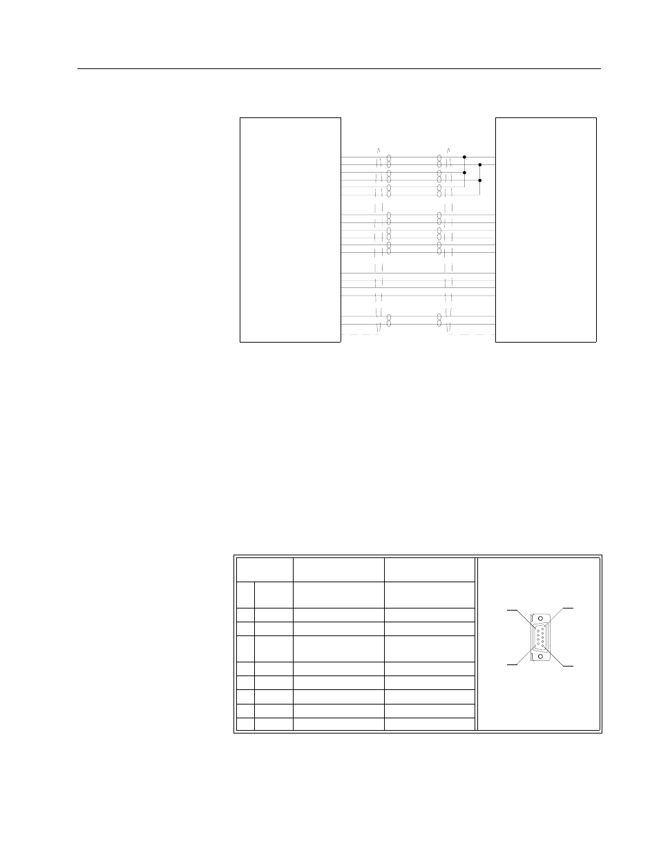
Figure 6.38
ULTRA 100 Series Motor Encoder Connections
MOTOR
ENCODER
Drive
EPWR
ECOM
EPWR
ECOM
EPWR
ECOM
AM+
AM-
BM+
BM-
IM+
IM-
HALL A
HALL B
HALL C
ABS
TS+
TS-
J2-1
J2-2
J2-3
J2-4
J2-5
J2-6-
J2-7
J2-8-
J2-9
J2-10
J2-11
J2-12
J2-13
J2-14
J2-15
J2-16
J2-19
J2-20
+5V
COM
A+
A-
B+
B-
Z+
Z-
HALL A
1
HALL B
1
HALL C
1
ABS
2
THERMOSTAT+
THERMOSTAT-
NOTES:
1. For encoders with differential Hall ouputs (A+, A-, B+, B-, C+ and C-) connect
only the + outputs to the drive.
2. The ABS signal is only available on selected Allen-Bradley encoders.
Table 6.23:
J1 Controller Pin-Outs
Pin & Sig-
nal
Description
Description
1 RCV(+
)
Receive (+)
RS-485 (four wire)
2 RCV
Receive
RS-232
3 XMT
Transmit
RS-232
4 XMT(+
)
Transmit (+)
RS-485 (four wire)
5 COM
+5 VDC Common
6
Reserved
a
7 RCV(-) Receive (-)
RS-485 (four wire)
8 XMT(-) Transmit (-)
RS-485 (four wire)
9
Reserved
a
a. Do not connect any device to J5-6 or J5-9 except a TouchPad.
pin 5
pin 6
pin 9
pin 1