Hall offset, Startup commutation, Step abs/index – Rockwell Automation 1398-DDM-xxx ULTRA 100 Series Drives Installation Manual User Manual
Page 264: Hall/index, and
Publication 1398-5.2 – PDF 1997
D-10
Creating Custom Motor Files
Hall Offset
The Hall offset specifies the offset of the Hall feedback signals
relative to the Allen-Bradley standard. The drive uses the Hall offset
to determine the commutation angle at startup. Hall offset is specified
as a value in the range from 0 to 359 electrical degrees.
The Hall signals, as well as the line-to-line back-EMF voltages, must
sequence according to the Allen-Bradley standard (refer to Figure D.2
and the “Motor Phasing” on page D-3). The Hall offset value is the
value the drive uses to correct for Hall signals that are shifted from the
line-to-line back-EMF.
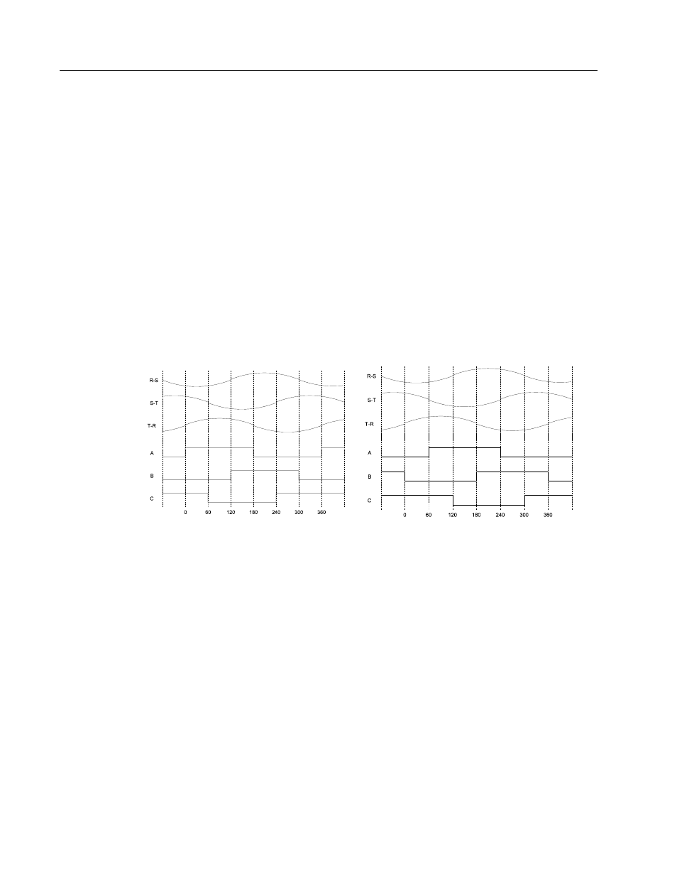
Figure D.5(a) shows the Allen-Bradley standard for orientation of the
Hall signals to the line-to-line back-EMF voltages. Figure D.5(b)
shows an example of a 60
o
Hall offset from the standard location.
Startup Commutation
The startup commutation list box specifies the type of commutation to
be used at startup. The choices are:
●
6-Step ABS/Index,
●
8-Step ABS/Index,
●
Hall/Index, and
●
Hall/Hall.
The different types of startup are identified by their initial and final
commutation angle measurement. For example, the 6-Step ABS/Index
startup uses the 6-Step ABS for the initial commutation angle
measurement, and the index signal for the final commutation angle
measurement.
Figure D.5
Hall Offsets
Intro
Intro
Intro
(a) Allen-Bradley Hall Location (0
o
Offset)
(b) Non-Standard Hall Location (60
o
Offset)