Connection diagram, Configuration, Position follower (step up/down controller) – Rockwell Automation 1398-DDM-xxx ULTRA 100 Series Drives Installation Manual User Manual
Page 139: Connection diagram configuration
Publication 1398-5.2 – PDF 1997
Application and Configuration Examples
8-25
Connection Diagram
Configuration
Carefully check all connections before entering these parameters.
1. Switch the AC Power to ON and verify:
• Status LED is green. Refer to “Status Indicator” on page 10-1
for an explanation of the display codes.
2. Start ULTRA Master on the PC.
3. Choose
Cancel
from the Drive Select dialog box.
4. Select
P
C Set Up
from the Communications menu in
ULTRA Master to display the personal computer’s communica-
tion settings.
5. Verify the communications port settings of the PC match those of
the drive.
• If the settings are correct, select
OK
in the Port - Settings dia-
log box.
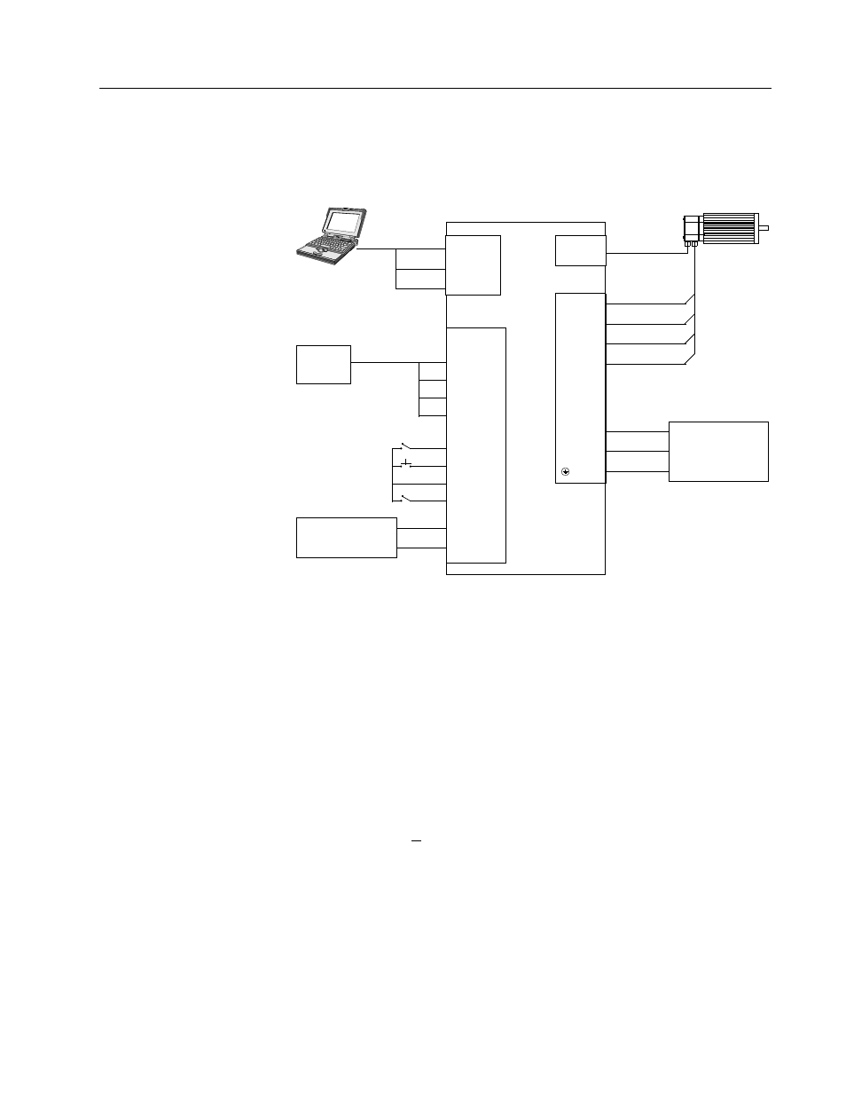
Figure 8.5
Position Follower (Step Up/Down Controller)
Connection Diagram
J1
14 CW+
15 CW-
16 CCW+
Close to ENABLE Drive
17 CCW-
Close to Follow
21 FAULT
26 I/O PWR
32 INPUT1
20 ENABLE
Step
Indexer
Note: Refer to Figure 6.34 and 6.35 for additional details
on the Control Interface Cable.
DRIVE
L1 3
L2/N 4
Gnd 5
100-240 VAC
50/50 Hz
Single Phase
Power Source
RESET
TB1
Phase R 6
Phase S 7
Phase T 8
Mtr Gnd 9
J2
Motor
Encoder
External I/O
12-24 VDC
Power Source
5 I/O PWR
6 I/O COM
J5
2 RCV
3 XMT
5 COM
XMT
RCV
COM