Connection diagram, Configuration, Registration indexing connection diagram – Rockwell Automation 1398-DDM-xxx ULTRA 100 Series Drives Installation Manual User Manual
Page 152: E figure 8.9, Connection diagram configuration
Publication 1398-5.2 – PDF 1997
8-38
Application and Configuration Examples
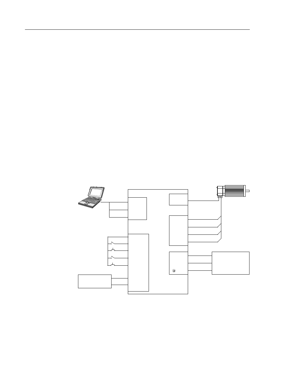
4. Connect the Index Sensor to the drive as shown in the diagram.
5. Connect a jumper wire with a toggle switch between the following
pins:
• J1-20 (ENABLE) and J1-26 (I/O PWR)
• J1-32 (INPUT1) and J1-26 (I/O PWR)
• J1-33 (INPUT2) and J1-26 (I/O PWR)
• J1-21 (FAULT RESET) and J1-26 (I/O PWR).
These connections provide manual control for enabling or
disabling the drive and resetting faults. The figure below shows
the jumper, including normally open toggle switches.
6. Connect an external 12 to 24 VDC power source for powering I/O
to J1-5 (I/O PWR) and J1-6 (I/O COM).
7. Connect the drive to a single phase 100-240 VAC, 50/60 Hz power
source.
Connection Diagram
Configuration
Carefully check all connections before entering these parameters.
1. Switch the AC Power to ON and verify:
Figure 8.9
Registration Indexing Connection Diagram
J1
26 I/O PWR
20 ENABLE
21 FAULT
32 INPUT1
Close to ENABLE Drive
Close to RESET Fault
J4
DRIVE
TB1
2 RCV
3 XMT
5 COM
L1 3
L2/N 4
Gnd 5
XMT
RCV
COM
100-240 VAC
50/50 Hz
Single Phase
Power Source
TB1
Phase R 6
Phase S 7
Phase T 8
Motor Gnd 9
J2
Motor
Encoder
RESET
Close to Start INDEX
Close for Registration
Sensor
33 INPUT2
External I/O
12-24 VDC
Power Source
5 I/O PWR
6 I/O COM