Electrical installation – Festo HSW-...-AP/AS User Manual
Page 46
HSW−...−AP/A S
Festo HSW−...−AP/AS 0812b English
46
Electrical installation
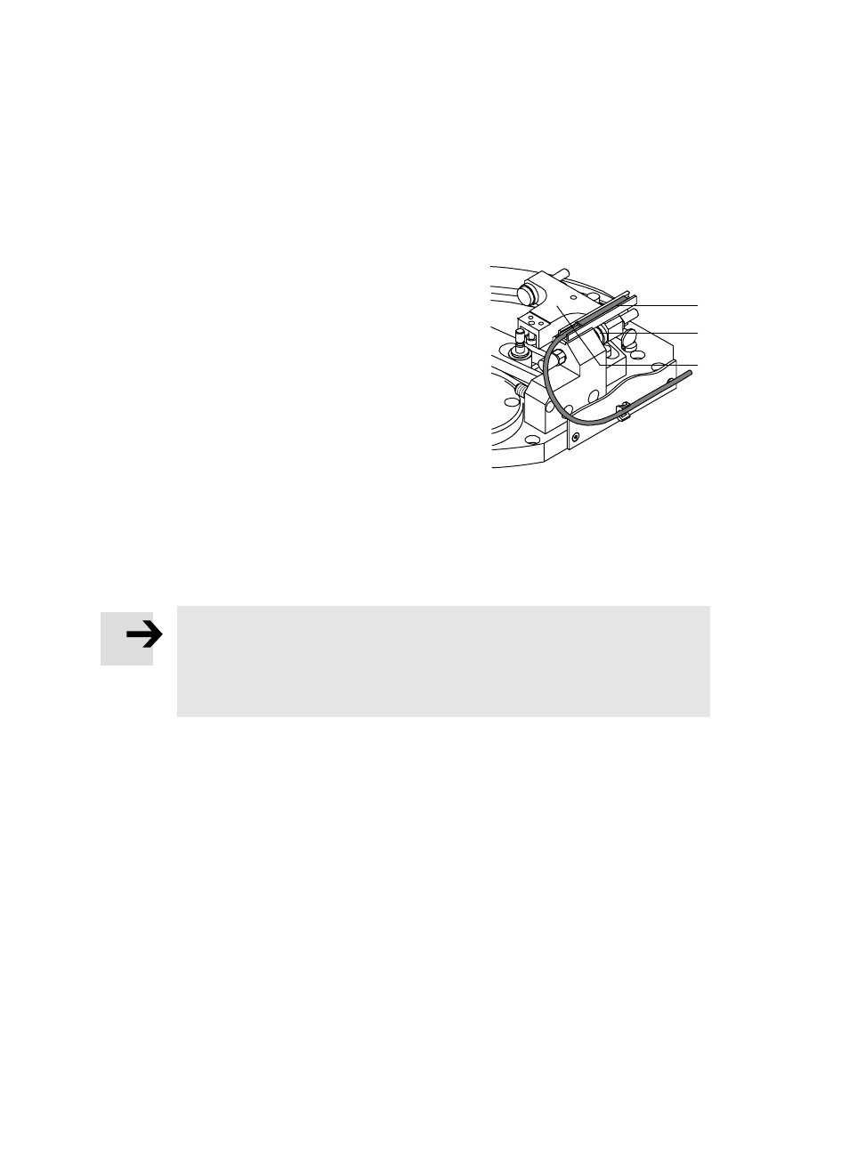
Using proximity switches SME/SMT−8 for
scanning the end positions:
1. Remove the protective cover of the
handling module.
2. Make sure that the shock absorbers are
screwed in completely (as supplied from
the factory in HSW−12/16).
3. Push the proximity switch into the groove
of the sensor rail (A).
The electrical proximity switch is triggered
by magnets in the stop screw (B) and in
web (C) (in HSW−10).
4. Fasten the proximity switch in the end position. Subsequent adjustment of the
shock absorbers is not necessary.
5. Fasten the protective cover of the handling module.
Please note
The cables of the proximity switches must not lie in the working range of the
handling module.
S Secure the cable using cable straps. Route the cable away to the side along
the guide rail.
Fig. 20
(A)
(B)
(C)
- Pneumatic linear cylinders ADN, AEN, ADNP (64 pages)
- KP (24 pages)
- DGC-K-18 … -80 (4 pages)
- SMT-8F-PS-24V-K0,3-M8D (2 pages)
- SMT-10F-PS-24V-K0,3L-M8D (2 pages)
- YSR-...-C (6 pages)
- DGC-8 ... 63-... (24 pages)
- DGC(I)-...-GP (2 pages)
- SME-10F-DS-24V-K0,3L-M8D (2 pages)
- KYC (2 pages)
- DADP-DGC (2 pages)
- DGC(I)-18...40-...-KF-...-GP-... (2 pages)
- DGC-HD (88 pages)
- SIES-8M-..-24V-.-.-... (2 pages)
- SLG−Z−... (88 pages)
- SLG−... (100 pages)
- SMT-8-PS-K-LED-24-B (2 pages)
- SMT-8-PS-S-LED-24-B (2 pages)
- DGP(L)-…-B (24 pages)
- SME-8-K-…-LED-24 (2 pages)
- DG..−...−GA, FDG−...−GA (40 pages)
- DGPI(L)−...−AIF (112 pages)
- DGO−...−A−B (88 pages)
- DRRD-...-PS1 (4 pages)
- DRRD-12 ... 63 (88 pages)
- DRRD-08/10 (4 pages)
- DSL-16 … 40-270-…-B (12 pages)
- DGSL (24 pages)
- SMT-10F-NS-24V-K2,5L-OE (2 pages)
- HMP−...−KP−... (76 pages)
- HMP−...−B−... (56 pages)
- HMP-...-AD/-EL (12 pages)
- DFST (76 pages)
- CLR (100 pages)
- DMSP-... (80 pages)
- DHTG (112 pages)
- BV-50-40 (4 pages)
- DFPI-...-...-ND2P-E-P-G2 (4 pages)
- DFPI-...-...-ND2P-C1V-...-A (5 pages)
- DAPS..R..-F..-MW.. (5 pages)
- DAPS..R..-F..-MW.. (5 pages)
- DAPS..R..-F.. (5 pages)
- DAPS..R..-F.. (18 pages)
- DFPB (18 pages)
- YSRWJ-...-A (64 pages)