Drill pattern cycle – ACU-RITE CNC 3500i User Manual
Page 183
ACU-RITE 3500i
157
7.
2
C
a
n
n
e
d
C
y
c
le
s
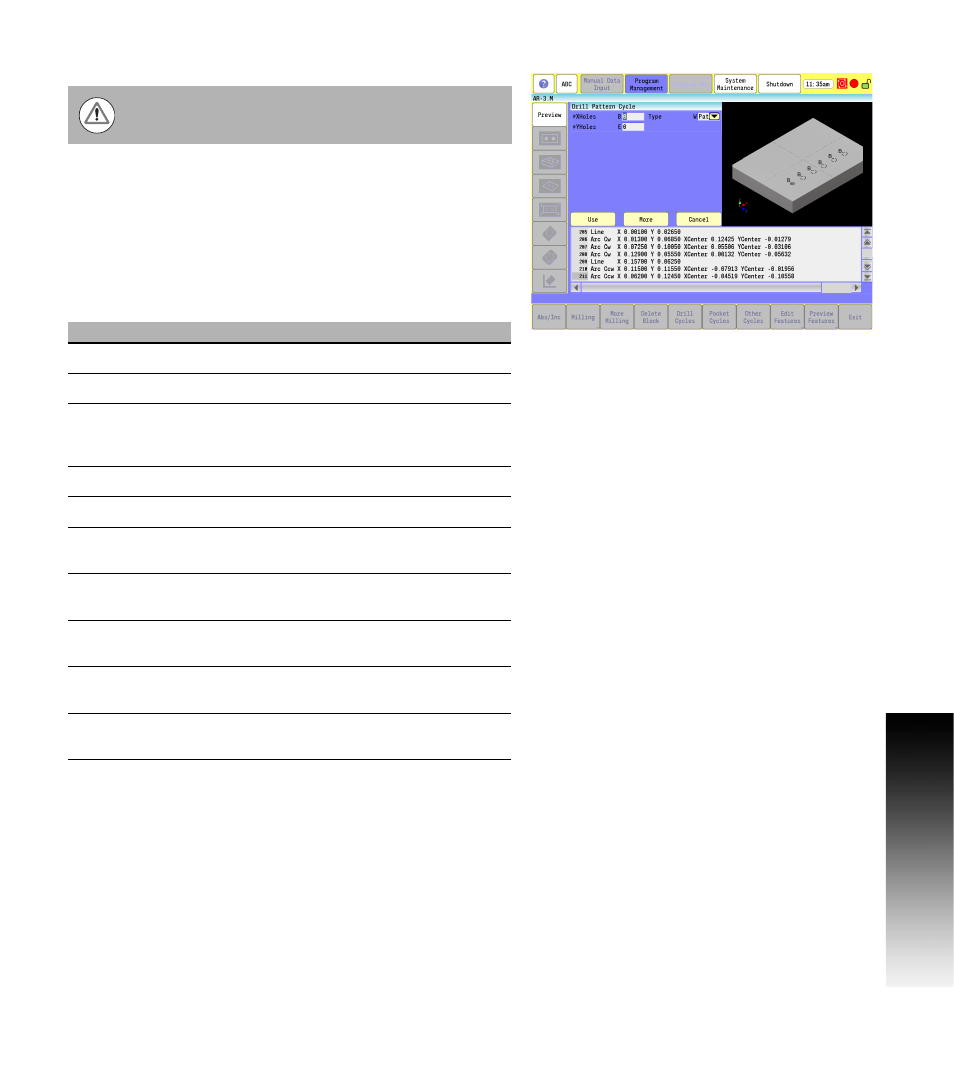
Drill Pattern Cycle
Use the automatic hole pattern cycle to program partial or full
pattern hole grids. You can use this for a corner pattern when holes
are required only on four corners. It calculates the hole locations
from the entered variables. You can also rotate the pattern around
the starting hole location. A drill cycle must be programmed prior to
this. You must cancel the cycle after the pattern is completed.
You can use [A and D] or [U and V], but not both combinations.
Positive and negative values are allowed in all variable words
except: B, and E.
G-code format: G179
Do not program RMS with the drill pattern cycle.
Field
Code
Description
# XHoles
B
Number of holes in X-axis. (Required)
# YHoles
E
Number of holes in Y-axis. (Required)
Type
W
Select Pattern for a drilled hole pattern, or
select Square for a perimeter drilled hole
pattern.
XStart
X
Absolute X position of start hole. (Required)
YStart
Y
Absolute Y position of start hole. (Required)
XIncr
U
Increment between holes in X-axis. Can be
used instead of A.
YIncr
V
Increment between holes in Y-axis. Can be
used instead of D.
Angle
C
Angle to rotate the hole pattern. Default is
0 degrees (3 o'clock position).
X Length
A
Length of pattern in X-axis. If used, U
cannot be given.
Y Width
D
Width of pattern in Y-axis. If used, V cannot
be given.