Understanding the leds – Allied Telesis AT-WA7501 User Manual
Page 17
AT-WA7500 and AT-WA7501 Installation and User’s Guide
17
Multiple Service Sets: For 802.11g and 802.11a radios, you can assign up
to four service sets (and four SSIDs) to each radio, allowing each radio to
handle traffic for up to four separate virtual LANs (VLANs).
Telnet Gateway APpliance (TGAP): This feature lets the access point act
as a gateway for up to 128 TE2000 clients to communicate with up to eight
hosts. Using the TGAP also offers client session persistence.
Enhanced DHCP Server: You can configure the access point DHCP
server to provide IP addresses to only Allied Telesyn devices. This feature
helps prevent unauthorized access to the wireless network. You can also
configure the DHCP server to always provide the same IP address to a
DHCP client each time it requests one.
Instant On Server: This server provides the device-level distribution of
firmware, applications, and settings to wireless end devices that have the
Instant On client installed. Currently, this feature can only be used in
EasyADC systems.
Understanding
the LEDs
The AT-WA7500 and AT-WA7501 access points have five LEDs. To
understand the LEDs during normal use, see the next table. To use the
LEDs to help troubleshoot the radios, see “Troubleshooting the Radios” on
page 256.
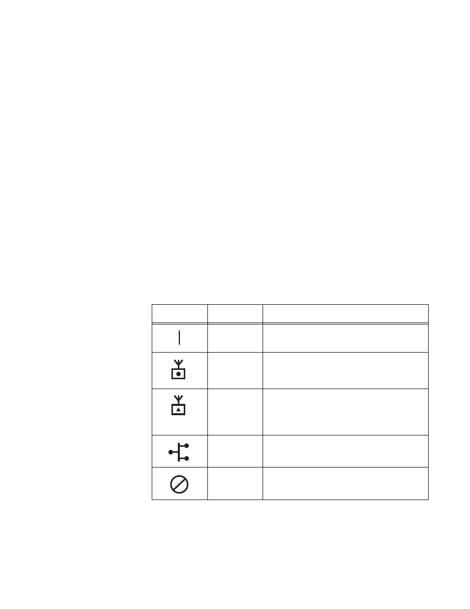
Table 2. LED Descriptions
Icon
LED
Description
Power
Remains on when power is applied.
Wireless #1
Blinks when a frame is transmitted or
received on the radio port for the radio
installed in radio slot 1.
Wireless #2
Blinks when a frame is transmitted or
received on the radio port for the radio
installed in radio slot 2 (if a second radio
is installed).
Wired LAN
Blinks when a frame is transmitted or
received on the Ethernet port.
Root/error
Blinks if this device is configured as the
root. It remains on if an error is detected.