Changing the manual do name and specified output, Index, Changng the manual do name and specfed output – Yokogawa DAQWORX User Manual
Page 71
2-41
IM WX103-01E
1
2
3
4
5
Index
Logger
Changng the Manual DO Name and Specfed Output
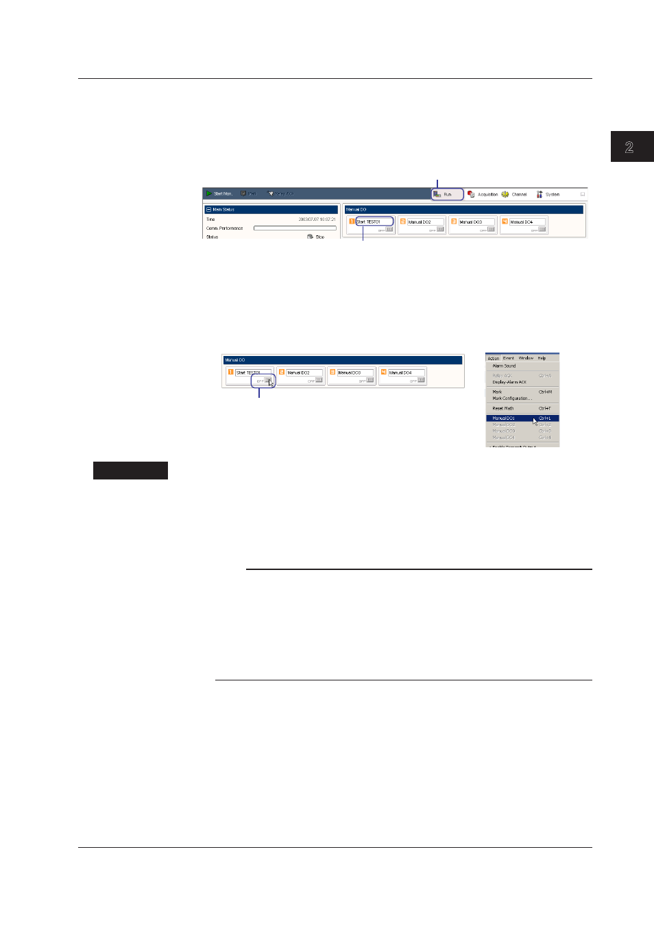
1. Click Run. The Run screen opens.
Changng the Name
2. While data monitoring is stopped, click the manual DO button name box shown in
the Manual DO area and enter the name.
Click here.
Click here and enter the name.
Output ON/OFF Operaton
The procedure below can be carried out when data is being monitored.
2. Click the manual DO button or choose Manual DO1 to Manual DO4 from the Action
menu.
The output turns ON, and the word “OFF” on the manual DO button changes to “ON.”
If “ON” is displayed, the output is turned OFF, and the word “ON” changes to “OFF.”
Click here.
or
Explanaton
Alarm Reference Channel Range
The alarm detection of multiple measurement channels and math channels can be
assigned to a single DO channel. When an alarm occurs on any of the assigned
channels, alarm output is activated. A range of consecutive channel numbers are
assigned. The range can span over units.
Note
• The alarm detection in the unit and the DO output is processed within the unit. Therefore, the
DO output continues even when the connection to the PC is cut off. If the alarm reference
channel range spans over multiple units or if the digital output module is not available in the
same unit, alarm detection is performed on the PC. In this case, alarm detection stops when
the connection is cut off. In addition, even when the connection is established, the alarm
detection interval may slow down.
• Alarms other than those on measurement channels do not function when not connected to
the PC.
Dgtal Specfed Output Other Than Alarm Output
The digital output can be enabled for the following causes.
• Manual DO [manual]
The relay contact signal of specified DO channels are turned ON/OFF collectively
when you click the manual DO button shown on the Run screen or when you choose
Manual DO1 to Manual DO4 from the Action menu.
• FAIL Output [Fail]
Outputs a relay contact signal when an error occurs in the main module CPU of a unit
containing a digital output module.
When the CPU is normal, the relay is energized and FAIL output is ON. When the
CPU is abnormal or if a power failure occurs, it is OFF.
2.7 Dgtal Output