2 mxlogger operation guide, Flow of operations during installation, 2 mxlogger operation guide -4 – Yokogawa DAQWORX User Manual
Page 11: Flow of operations during installation -4, 2 mxlogger operaton gude, Flow of operatons durng installaton
1-4
IM WX103-01E
1.2
MXLOGGER Operaton Gude
Flow of Operatons durng Installaton
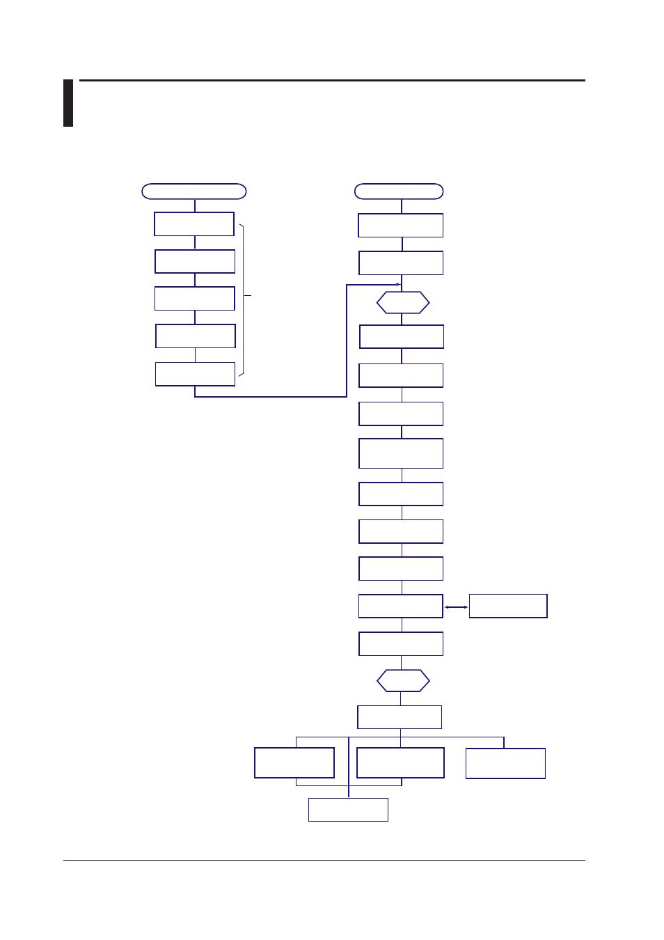
The figure below shows the general flow of operation when the MX100 is installed
initially.
Wire the input/
output modules
Operations on the MX100
Operations on the PC
Connect the
network cable
Connect the power
cord
Turn ON the power
switch
Set up the
MXLOGGER
Set the network
parameters of the PC
Start the
logger
Search the MX100/
configure the network
Configure the system
Set the data
acquisition condition
Set the measurement
conditions/set
the computation
Acquire/Monitor the data
and monitor the alarm
Change the display
conditions
Record the data
Install the MX100
See the Installation
and Connection Guide.
Section 2.1
Section 2.2
Section 2.3
Sections 2.4 and 2.5
Section 2.10
Section 2.10
Section 2.12
Section 3.4
Start the
Viewer
Display the recorded
data
Perform statistical
computation over an
area of data
Read values using
cursors
Convert the data
format
Print the displayed
data
Sections 3.1 and 3.2
Section 3.3
Section 3.7
Section 3.8
Section 1.5
Section 1.5
Section X.X indicates the referred
sections in this manual.
*The available digital
(DO) outputs are alarm
output, manual DO, fail
output, and error output.
The Installation and Connection Guide (IM
MX100-72E)
is an abridged manual provided with
the MX100 main module. The Installation and
Connection Guide
does not explain all the
functions and operations. It also does not cover the
details of the precautions and limitations of usage.
For a detailed explanation, see the MX100 Data
Acquisition Unit User's Manual (IM MX100-01E)
contained in the manual CD-ROM.
See the DAQWORX Installation
and Operation Guide (IM
WX1000-01E).
Set the appropriate IP address,
subnet mask, and default
gateway of the PC.
Search all connected MX100s and
configure the network parameters
such as the IP address of the
connected MX100s.
Select the MX100 to be connected,
select the acquisition interval of
each input module, etc.
Select the acquisition interval to be
used, select the record interval, set
record start/stop conditions, etc.
Set the transmission
output
Section 2.8
Set analog/PWM output and others
Set the alarm
Section 2.6
Set the alarm
See section 2.7 for digital output*
settings.
Set up events
Section 2.9
Set individual events
Set the input mode,
measurement range,
measurement span, etc.