7 external interface breakout board, External interface breakout board – Teledyne LeCroy Merlin II - Users Manual User Manual
Page 25
15
Merlin II Protocol Analyzer User’s Manual
CATC
SW Version 2.50
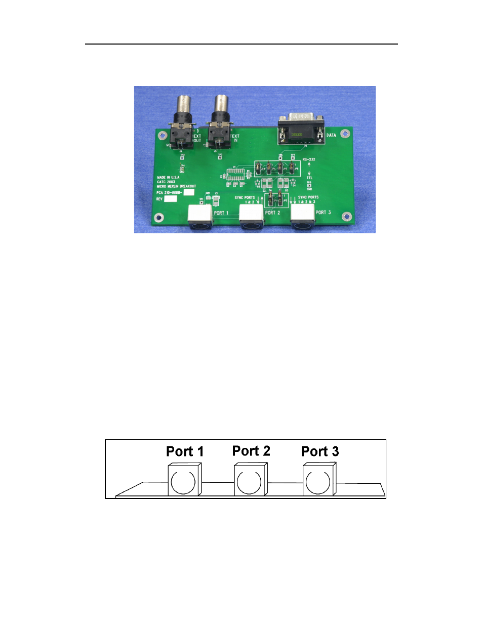
2.7 External Interface Breakout Board
The External Interface Breakout Board is an accessory that allows standard,
LV TTL signals to be connected to the analyzer for triggering. The breakout
board consists of two BNC connectors for "EXT IN" and "EXT OUT"
signals. The EXT IN connector can be used to import trigger signals from
other devices. the EXT OUT connector can be used to export trigger signals
to trigger other devices such as oscilloscopes or logic analyzers or to export
the external clock for clock calibration using a frequency counter (see
Appendix A).
Drive strength for all outputs is about 30mA high (@2V) and 60 mA low
(@0.5V). Inputs can handle 0 to 5.5V. Inputs above 2V are detected as logic
high; inputs below 0.8V are detected as logic low.
The analyzer connects to the first of three mini DIN ports ("Port 1") on the
Breakout Board. Each signaling pin is isolated by a 100
Ω
series resistor and
a buffer inside the Analyzer unit.
Please make sure that the jumpers JP1 and JP2 on the breakout board are set
to Position 1.
Mini DIN connectors on the back of the Break-out board.