Appendix b: hci probe description – Teledyne LeCroy Merlin II - Users Manual User Manual
Page 177
167
Merlin II Protocol Analyzer User’s Manual
CATC
SW Version 2.50
Appendix B: HCI Probe Description
The HCI Probe is used to connect the HCITracer software to an IUT. If
more IUTs are to be monitored, additional HCI Probes should be used.
HCITracer will support up to three HCI probes. It is also possible to forego
the probe and connect an IUT to several ports on the host PC. A direct
connection between the IUT and the host PC is useful when the PC has high
speed serial ports.
The HCI probe can be used in several configurations.
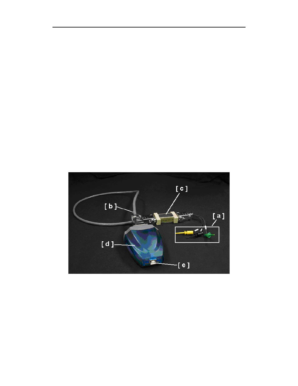
The HCI probe consists of three cables, an RS232 to USB converter, and a
TTL to RS232 converter. These components are shown in the photo below.
Depending on your test environment, you may need to use all of the
components or just some of them.
To monitor RS232 signalling, you use all of the components. To monitor
UART signalling, you omit the TLL to RS232 converter ("c" in the photo).
The steps for connecting the probe components are listed after the following
descriptions.
The five probe components consist of:
[ a ]
HCITrace Probe Cable - This cable connects directly to the
IUT. This cable has three leads:
•
Gnd – Connects to the reference/ground wire
•
Host – Connects to the wire that carries the down-link
traffic from the host to the controller.
•
BTC– Connects to the wire that carries the up-link traffic
from the controller to the host.