1 explanation of signal names, Explanation of signal names – IAI America RCP2-CF User Manual
Page 64
44
5.1.1 Explanation
of Signal Names
The following explains the signal names, and gives a function overview of each signal.
In the explanation of operation timings provided in a later section, each signal is referenced by its self-
explanatory name for clarity. If necessary, however, such as when marker tubes are inserted as a termination of
the flat cable, use the signal abbreviations.
PIO pattern = “0: [Conventional],” “1: [Standard],” “2: [64-point positioning],” “3: [2 zone output
signals]”
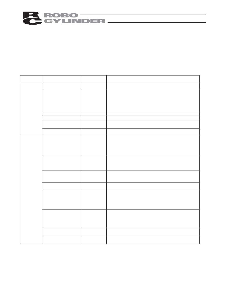
Category Signal
name
Signal
abbreviation
Function overview
Start
CSTR
Movement is started at a rise edge of this signal.
Command position number
PC1
PC2
PC4
PC8
PC16
PC32
The target position number is input.
A command position number must be specified by 6 ms before the
start signal (CSTR) turns ON.
*Pause
*STP
ON: Actuator can be moved, OFF: Actuator decelerates to a stop
Home return
HOME
The actuator moves in the positive direction while this signal is ON.
Servo ON
SON
The servo remains ON while this signal is ON.
The servo remains OFF while this signal is OFF.
Input
Alarm reset
RES
An alarm is reset at a rise edge of this signal.
Completed position number PM1
PM2
PM4
PM8
PM16
PM32
The relevant position number is output when positioning has
completed.
The signal will turn OFF when the next start signal is received.
It is used by the PLC to check if the commanded position has
definitively been reached, and also to provide a position interlock,
etc.
Moving
MOVE
This signal turns ON while the actuator is moving, and turns OFF
while it is stopped.
It is used for operation check and also to determine whether the load
is contacted during push & hold operation.
Position complete
PEND
This signal turns ON when the target position was reached and the
actuator has entered the specified in-position range.
It is used to determine whether positioning has completed.
Home return completion
HEND
This signal is OFF immediately after the power is input, and turns
ON when home return has completed.
Zone ZONE1
ZONE2
This signal is output when home return has completed and the
current actuator position is inside the range set by the applicable
parameter.
It can be used as a limit switch at an intermediate point or as a
simple ruler during push & hold operation.
Ready
SRDY
This signal is always output once the servo is turned ON and the
controller is ready to operate.
The signal is synchronized with the lit/unlit status of the “RUN” LED
on the front panel of the enclosure.
It is used by the PLC to determine when it can start operation.
*Alarm
*ALM
This signal remains ON in normal conditions of use and turns OFF
when an alarm generates.
Output
*Emergency stop
*EMGS
This signal is enabled on a “built-in cutoff relay” controller.
OFF: Emergency stop has been actuated