Large-capacity controller (6 a) – IAI America RCP2-CF User Manual
Page 61
41
[Large-capacity controller (6 A)]
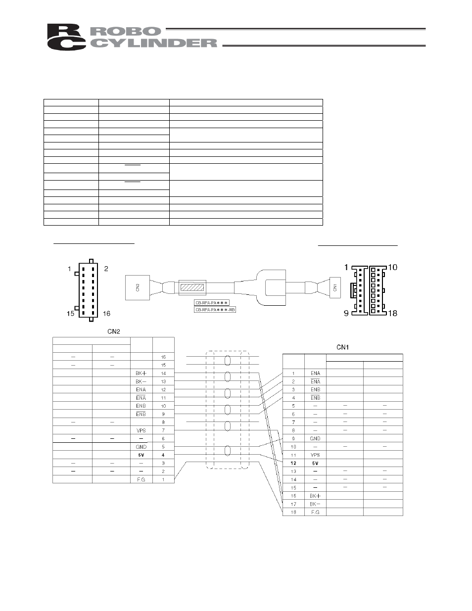
Connect the encoder extension cable to the ENC connector.
Signal table for the controller-end connector (CN2)
Pin No.
Signal abbreviation
Description
1 F.G
Shielded
wire
2 -
(Not
used)
3 -
(Not
used)
4 5V
Encoder
power
output
5 GND
6 -
(Not
used)
7
VPS
Encoder control signal output
8 -
(Reserved)
9
EN B
Encoder differential signal phase-B input
10 EN
B
11
EN A
Encoder differential signal phase-A input
12 EN
A
13
BK –
Negative side of the brake power supply
14
BK +
Positive side of the brake power supply
15 -
(Reserved)
16 -
(Reserved)
Housing:
PHDR-16VS
(J.S.T.
Mfg.)
Contact:
SPHD-001T-P0.5
Housing: XMP-18V (J.S.T. Mfg.)
Contact: BXA-001T-P0.6
Retainer: XMS-09V
Controller end
CN2 pin assignments
Actuator end
CN1 pin assignments
Purple
White (with purple)
Blue
White (with blue)
Yellow
White (with yellow)
Green
Red
White (with red)
Ground
(Reserved)
(Reserved)
Cable color
Red
Gray
Brown
Green
Purple
Pink
Yellow
Blue
Orange
(Reserved)
Cable color
Robot cable
Blue
White (with blue)
Yellow
White (with yellow)
Standard cable
Brown
Green
Purple
Pink
Ground
Blue
Yellow
Orange
Red
Gray
Ground
Green
Red
Purple
White (with purple)
Ground
White (with red)
Standard cable
Robot cable
Robot cable
Standard cable
Signal
abbreviation
Signal
abbreviation
Pin No.
Pin No.