2 external connection diagram, External connection diagram – IAI America RCP2-CF User Manual
Page 39
19
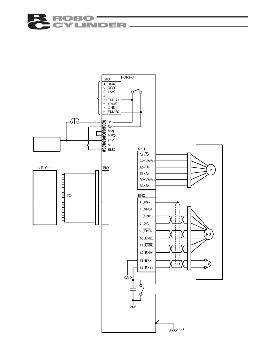
4.1.2 External
Connection
Diagram
An example of standard wiring is shown below.
(Note) The encoder cable shown in the example is the standard cable for the controller with the maximum
current of 2 A.
As for the robot cable or the cable for the large-capacity type, refer to 4.4.2, “Encoder Extension Cable.”
Blue
Black
White
Red
Black
Green
Orange (black 2)
Orange (red 2)
Yellow (black 1)
Yellow (red 1)
White (black 1)
White (red 1)
Light blue (black 1)
Light blue (red 1)
Controller
Connected to teaching
pendant or PC
External EMG switch
Input power supply
24 VDC
24V
0V
FG
Host system
flat cable
Refer to 4.3, “Connecting the
I/O Cables,” for the connection
of I/O signals.
(PORT switch)
Terminal block
Actuator
Motor
Encoder
Holding
brake
Brake release switch
Tighten together with the
mounting screw.
Yellow