Telos Zephyr Xstream User Manual
Page 67
USER’S MANUAL
Section 3: GUIDED TOUR of the HARDWARE 55
• Bridging ≥ 10 K ohm impedance
The inputs are designed to be sourced from balanced, signals. Older equipment (or some
microphones) with a transformer output stage may need a terminating resistor (usually 600
ohms) across pins 2 and 3, consult the manual for your equipment for how to use it with high
impedance inputs.
Unbalanced sources may be used by connecting pins 3 to the source ground, while the signal
high is connected to pin 2. We recommend leaving pin 1 (ground) unconnected, as this
arrangement will prevent the possibility of ground loops.
h
HOT TIP!
The signal fed to these inputs should normally be a mix-minus or those monitoring from the far
end will hear a delayed version of their own audio coming back to them (i.e. an echo).
See section 10.3 for details on dealing with delay and mix-minus.
?
CURIOSITY NOTE!
The Telos Zephyr Xstream the more common pin-outs for three pin XLR inputs & outputs. You
can easily remember the correct signals when wiring connectors using the phrase “George
Washington Bridge.” Pin 1 = G = Ground, Pin 2 = W = “+” = White (typical color in mic
cable, if there is no white there will be a red conductor), and Pin 3 = B = “-” = Black.
Local Monitor Mix 1 Outputs
See the Section 3.3 for information on this headphone level output, located on the front panel.
On units with rev F audio boards this mix can be output on the XLRs instead of Local Monitor
Mix 2.
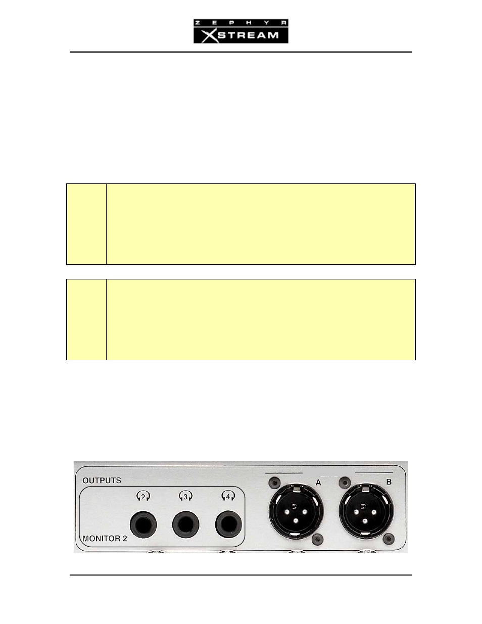
Local Monitor Mix 2 Outputs
MONITOR MIX