Telos Zephyr Xstream User Manual
Page 45
USER’S MANUAL
Section 3: GUIDED TOUR of the HARDWARE 33
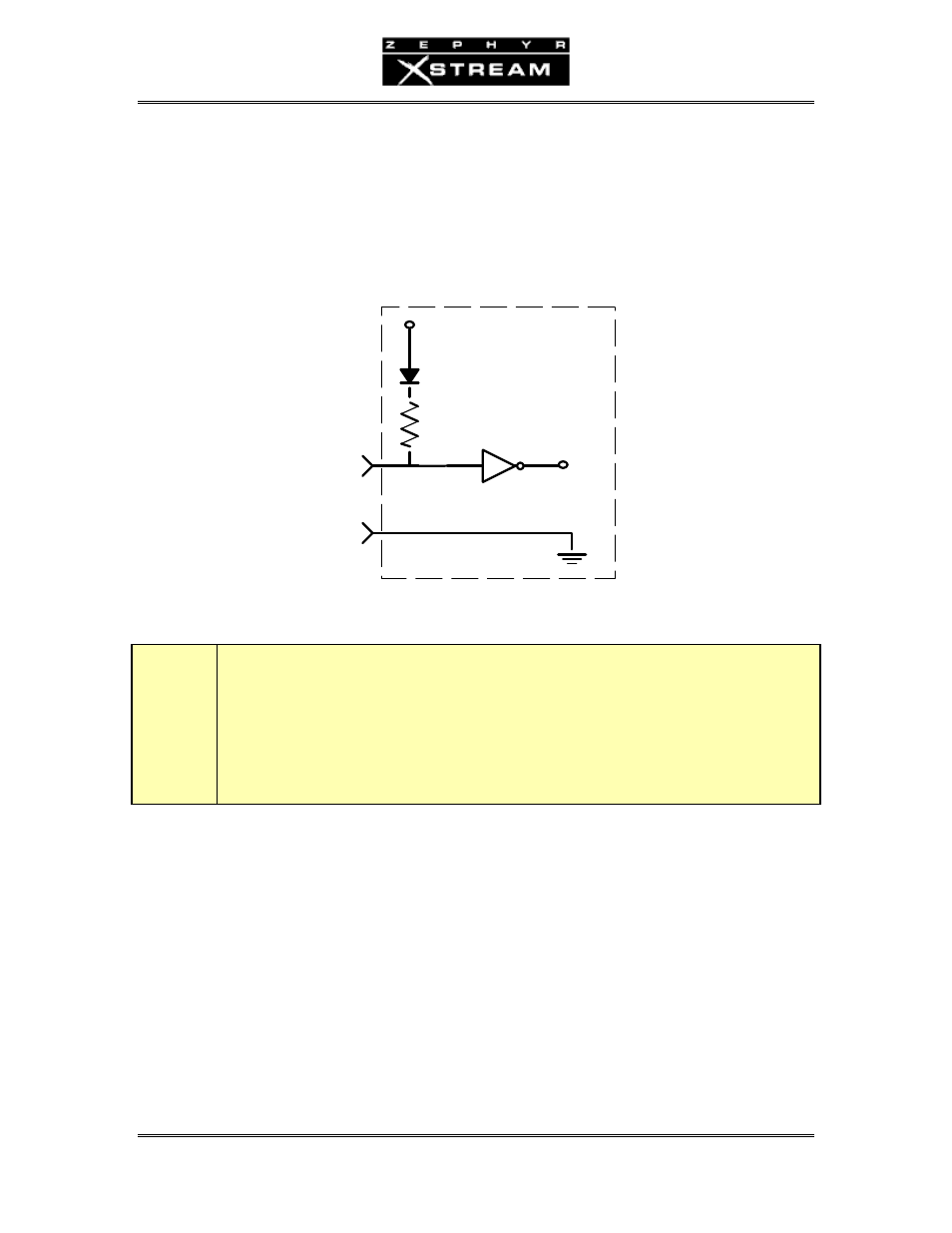
Parallel Inputs 0‐7
All inputs are specially treated to accept either a voltage (up to 24 VDC), or a closure to ground,
which may be provided by switches, relays, or logic outputs. The inputs are active low. In other
words, shorting the input to ground causes it to become true (i.e. "asserted").
A built in 1kΩ pull up resistor is provided so TTL outputs can be directly interfaced. See below
for a simplified schematic of the input circuitry.
+5 VDC
(30 Volts max)
INPUT
PIN 25
Parallel logic input circuit
t
DEEP TECH NOTE!
The Zephyr Xstream’s “universal” logic input circuit (motherboard rev G and later) can be
used with switch or relay closures, voltage levels up to 24 Vdc, or logic outputs – either
“totem-pole” or open-collector.
The inputs can be transmitted to the far end Zephyr Xstream when using the Layer‐3, AAC, or
AAC‐LD coding modes. The inputs can also be used for local control functionality such as
triggering Dial Setups (Panic Dial). Refer to Section 11.5 (Detailed Menu Reference) for the menu
selections relating to these functions.
Analog Inputs & Outputs
Inputs (Send to Network)
These are Combo Connectors with XLR female and ¼” Tip‐Ring‐Sleeve (TRS) balanced female
inputs. The pin out is as follows: