Telos Zephyr Xstream User Manual
Page 32
USER’S MANUAL
Section 3: GUIDED TOUR of the HARDWARE 20
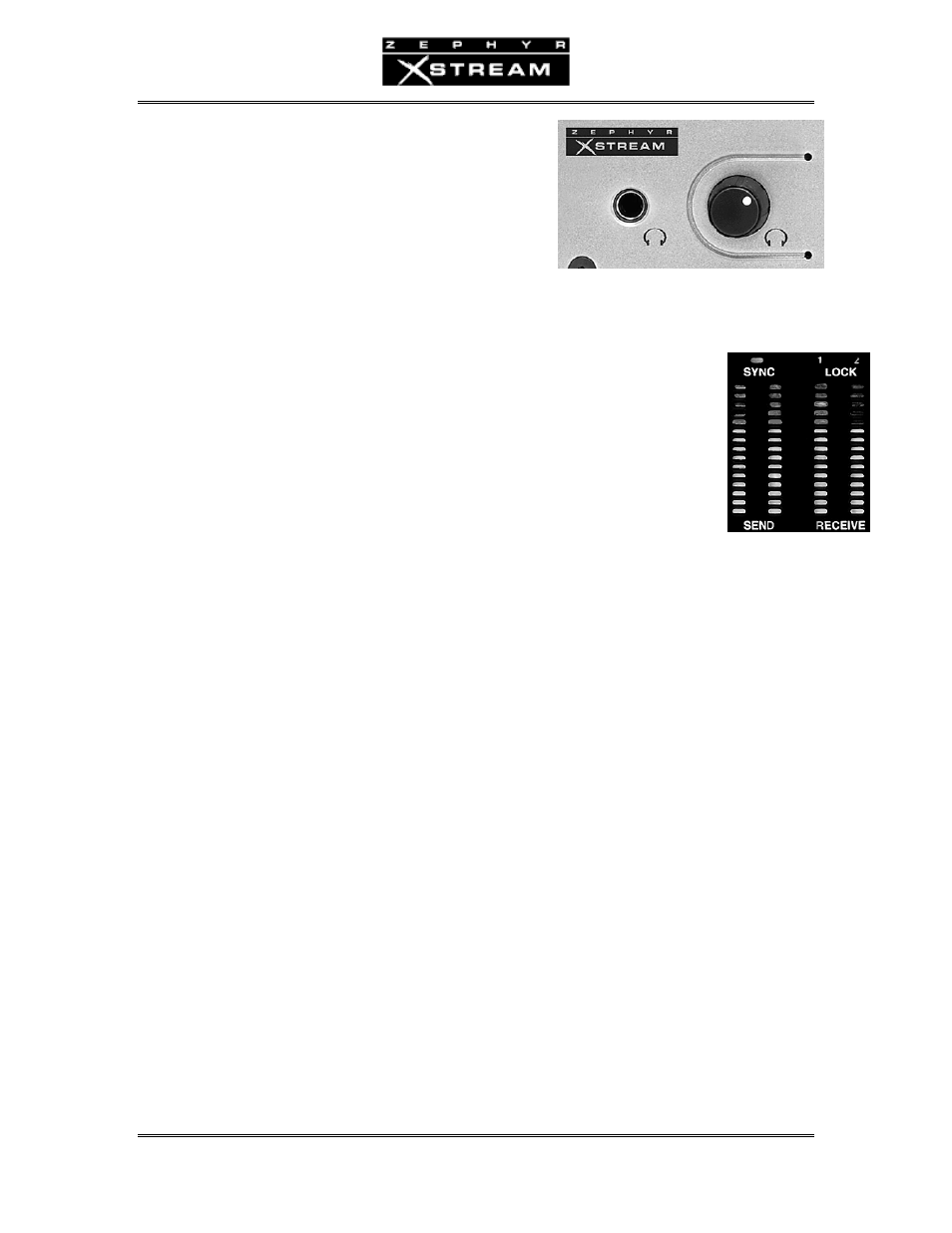
Headphone Jack & Volume Control
The front panel has a headphone jack near the left side.
The adjacent knob controls the level. This jack duplicates
the receive signal on the main outputs on the rear panel.
\
Meters and indicators
The following LEDs allow you to monitor the system status and audio levels:
Sync LED
The green Sync LED indicates, “all is well” with the system. It indicates that
certain clock signals are present and that the internal PLL is within its normal
range. This LED should normally be illuminated at all times if the internal ISDN
interface is functioning and selected as your Interface in the TEL Menu.
When the V.35/X.21 interface is present (and selected) the Sync LED will be
illuminated only if a valid external clock signal at the correct frequency for the Bit
Rate setting (in the CODEC menu) is present on one of the two V.35/X.21 ports.
When the Ethernet interface is selected, the Sync LED will blink while the Xstream’s clock works
to sync with the Xstream on the other side of the connection. Due to network conditions, it is
common for this light to be solidly on, then start blinking again as the clock readjusts.
Lock 1 & 2 LEDs
The green Lock 1 and Lock 2 LEDs represent the codec decoder status.
These will illuminate when a valid bitstream is received as follows: If a dual channel receive
mode is used (i.e. L3 Dual/Mono, or G.722) the Lock 1 LED represents that the decoder is locked
(or “framed”) to the incoming coded audio on “Line 1” while the Lock 2 LED represents a
decoder lock on an incoming audio stream on “Line 2”.
In the case of a stereo, or mono‐128, receive mode, both lock LEDs will illuminate only once a
compatible pair of bit‐streams are present on both “Lines”.
Send Bargraph
The Send Bargraph LEDs represent the level of audio into the coder section. This level is
effected by several factors: the output level of the device connected to the Zephyr Xstream; the
settings of the input level jumpers (see Section 5); the setting of the Level In option in the AUDIO
menu; and the setting of the Gain trim (may be called In Gain on early software versions) setting
in the AUDIO menu.
As with most digital equipment, these meters are calibrated in dBfs (decibel below full scale). In
other words, the top LED represents the clip point and the numbers are calibrated in dB below
full scale. Therefore it is essential that your levels be set to where the top LED is never lit.