Telos Zephyr Xstream User Manual
Page 170
USER’S MANUAL
Section 9: The V.35/X.21 Interface Option 158
* Xstream does not support separate TX and RX clocks. RX Clock signal is sent out as TX
Clock.
# RTS and DTR are permanently asserted “true”.
t
DEEP TECH NOTE!
The standard uses electrically balanced transmission for both clock and data (but not for the
special auxiliary signals, which are identical to RS-232). The transmit voltage level is ± 5.5V,
but receivers must handle wider swings.
X.21, a more modern standard, is also used for connections to synchronous digital data paths.
This standard specifies the much more reasonable DB‐15 connector. Fortunately, it is possible
to design an interface that accepts both V.35 and X.21 signals. This we have done with the
Zephyr Xstream, allowing connection to both types just by changing the interconnect cables.
The X.21 standard is frequently seen in Europe and other areas outside the USA & Canada. The
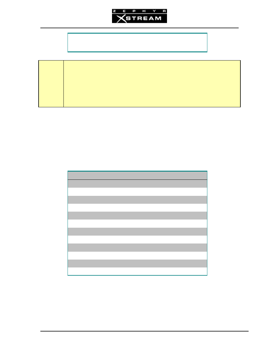
following Signals are provided at the X.21 end of the Telos cable:
X.21 CONNECTOR PIN-OUT
Pin
Description
Direction (Xstream ◄► DCE)
2 TX
Data
►
3 #
RTS
►
4 RX
Data
◄
5
CD (Carrier Detect)
◄
6 Clock
◄
8
Ground
9 /TX
Data
►
10 #
/RTS
►
11 /RX
Data
◄
13
/Clock
◄
# RTS and DTR are permanently asserted “true”.
CSU’s and DSU’s
CSU. Channel Service Unit. DSU. Data Service Unit. This is what the interface between the
Zephyr and digital channel is usually called. It converts the signals from the telephone line to the