Hcd-e1 – RAD Data comm HCD-E1 User Manual
Page 60
Chapter 3 - Front Panel Operating Instructions
HCD-E1
Installation & Operation Manual
3-2
Front Panel Controls, Connectors, and Indicators
11/01/00 19:52
10
8
E1 LOS
LOC REM LINE A LINE B
HDSL LOS
ALM
TST
CURSOR SCROLL ENTER
DCE
CONTROL
HCD-E1
HCD-E1
HCD-E1
HCD-E1
3
2
1
5
6
7
9
11
4
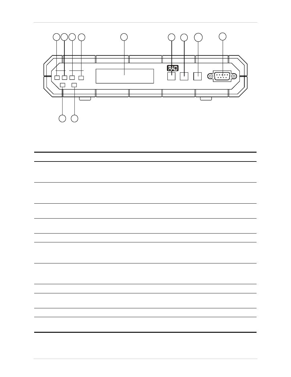
Figure 3-1 HCD-E1 Front Panel
Table 3-1 HCD-E1 Controls, Connectors and Indicators
No
Name
Type
Function
1
E1 LOS LOC
LED indicator
Lights when the local E1 port loses frame synchronization to
the incoming signal (in the UNFRAMED mode, the indicator
lights when the incoming signal is corrupted or missing)
2
E1 LOS REM
LED indicator
Lights when the equipment connected to the E1 port
reports loss of synchronization. This indication is not
available when the UNFRAMED mode is selected.
3
HDSL LOS
LINE A
LED indicator
Lights when the HDSL line A (line 1) circuits lose
synchronization to the incoming signal
4
HDSL LOS
LINE B
LED indicator
Lights when the HDSL line B (line 2) circuits lose
synchronization to the incoming signal
5
TST
LED indicator
Lights when a test is active
6
ALM
LED indicator
Lights when ON-state alarms (for explanation of the term
see Section 5.2, Status Indications and Alarms, in Chapter 5)
are stored in the HCD-E1 alarm buffer
7
Alphanumeric
display
Liquid crystal display (LCD) used to display messages and
status information. The display contains 2 rows of 16
characters each.
8
CURSOR
Push button
Used to move among the information fields on the LCD
9
SCROLL
Push button
Used to scroll among the available options displayed on the
LCD
10
ENTER
Push button
Used to confirm the changes made in HCD-E1 operation
11
CONTROL
DCE
Connector
Connection to control terminal