RAD Data comm HCD-E1 User Manual
Page 54
Chapter 2 - Installation and Setup
HCD-E1
Installation & Operation Manual
2-8
Installation and Setup
11/12/00 10:36
Setting the Sublink Interface Board Jumpers
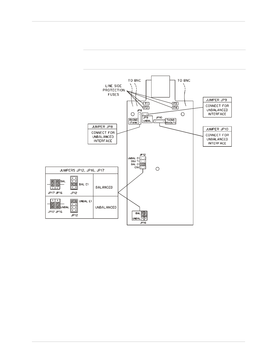
Figure 2-4 shows the component side of the E1 sublink interface board, as
seen after it is removed from the unit.
Note
The interface board has protection fuses for the surge protection circuits
located on the line side of the line isolation transformers. These fuses are also
identified in Figure 2-4.
JP17
Figure 2-4 E1 Sublink Interface Board, Internal Settings
Set the jumpers as follows:
Interface Selection Jumpers, JP9, JP12, JP16, and JP17
The jumpers JP9 and JP12 and the double jumper JP16-JP17 are used to
select the E1 sublink interface. All the jumpers must be always set to the
same position (either BAL or UNBAL).
•
For operation with the balanced interface:
− Set the jumper JP12 to BAL E1.
− Set the jumpers JP16 and JP17 to BAL.
− Disconnect the jumper JP9.