D.4 installation and operation – RAD Data comm HCD-E1 User Manual
Page 201
HCD-E1 Installation & Operation Manual
Appendix D - IR-ETH/Q Interface Module
Installation and Operation
D-3
D.4 Installation and Operation
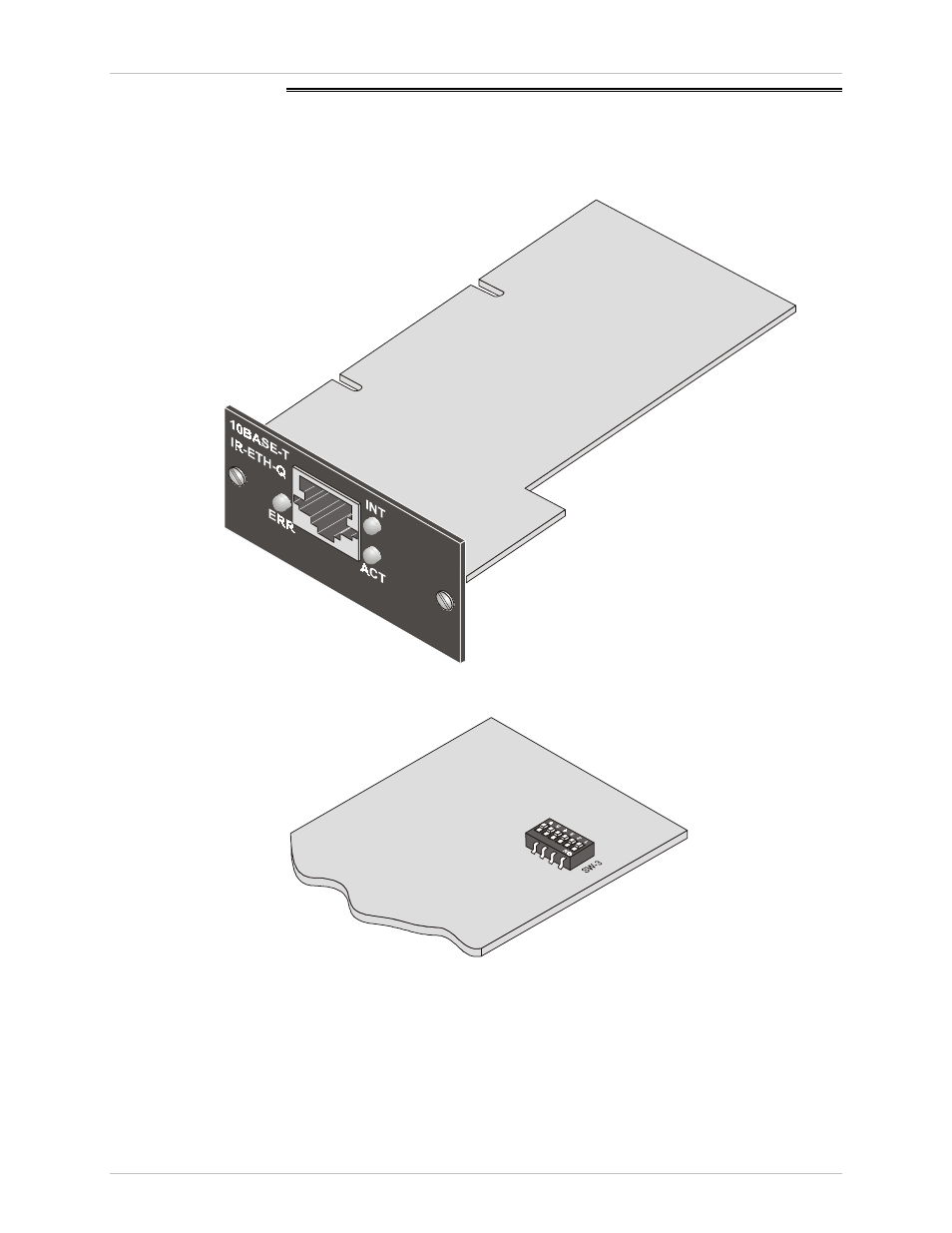
Figure D-3 shows the IR-ETH/Q rear panel. Figure D-4 shows the DIP switch,
which is located on the reverse side of the board.
Figure D-3 IR-ETH/Q Module Layout
Figure D-4 DIP Switch Location