RAD Data comm HCD-E1 User Manual
Page 31
HCD-E1 Installation & Operation Manual
Chapter 1 - Introduction
01/01/01 08:07
Functional Description
1-13
NETWORK
SIDE
E1
INTERFACE
DATA
EQUIPMENT
DATA
CHANNEL 2
INTERFACE
DATA
EQUIPMENT
DATA
CHANNEL 1
INTERFACE
E1
INTERFACE
CUSTOMER
SIDE (DTE)
DATA
CHANNEL 2
INTERFACE
DATA
EQUIPMENT
DATA
CHANNEL 1
INTERFACE
DATA
EQUIPMENT
HDSL LINE B
INTERFACE
HDSL LINE
INTERFACE
HDSL LINE B
INTERFACE
HDSL LINE A
INTERFACE
LOOPBACK
TIMING
INTERNAL
TIMING
CENTRAL HCD-E1
HDSL
LINE B
HDSL
LINE A
REMOTE HCD-E1
LOOPBACK
TIMING
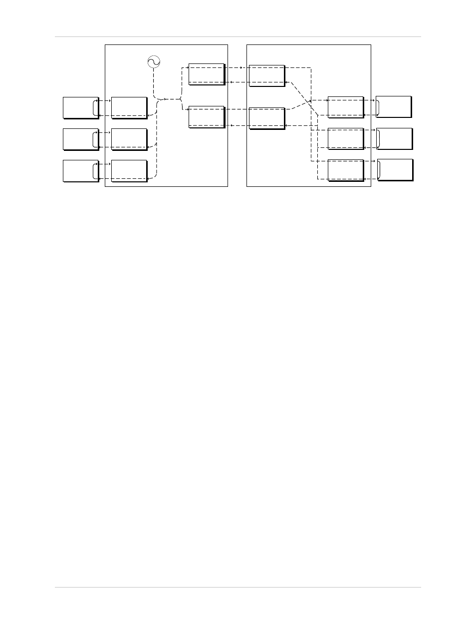
Figure 1-6 Flow of Timing Signals through HCD-E1 System in the Internal Timing Mode
HCD-E1 Configured as Remote Unit (NTU)
The HCD-E1 unit configured as NTU always locks its internal system timing
to the incoming HDSL signals, that is, to the timing of the unit configured as
central. The timing is derived from the clock signal recovered from line A; if
line A fails, HCD-E1 automatically switches to the clock signal recovered
from line B.
Data Channel Timing
The HCD-E1 data ports have three timing modes: DCE, DTE1 and DTE2.
•
In the DCE timing mode, the HCD-E1 data channel provides transmit
and receive clocks for the equipment connected to the data port.
•
In the DTE1 timing mode, the HCD-E1 data channel sends the receive
data accompanied by the receive clock, derived from the main system
clock, to the data equipment connected to the data port, and accepts
data according to the data equipment transmit clock.
•
In the DTE2 timing mode, the HCD-E1 data channel transmits and
receives data according to the clock signals provided by the equipment
connected to the data port. When using this clocking mode, the main
link timing must be locked to the clock signal supplied by the data port
interface. The DTE2 mode is not available on channels with X.21
interface.
Figure 1-7 shows a typical application which uses one of the data channels,
operating in the DTE2 timing mode, as the timing reference source, and
illustrates the flow of timing signals within the system.