C.4 installation and operation – RAD Data comm HCD-E1 User Manual
Page 195
HCD-E1 Installation & Operation Manual
Appendix C - IR-ETH Interface Module
31/12/2000 17:57
Installation and Operation
C-3
C.4 Installation and Operation
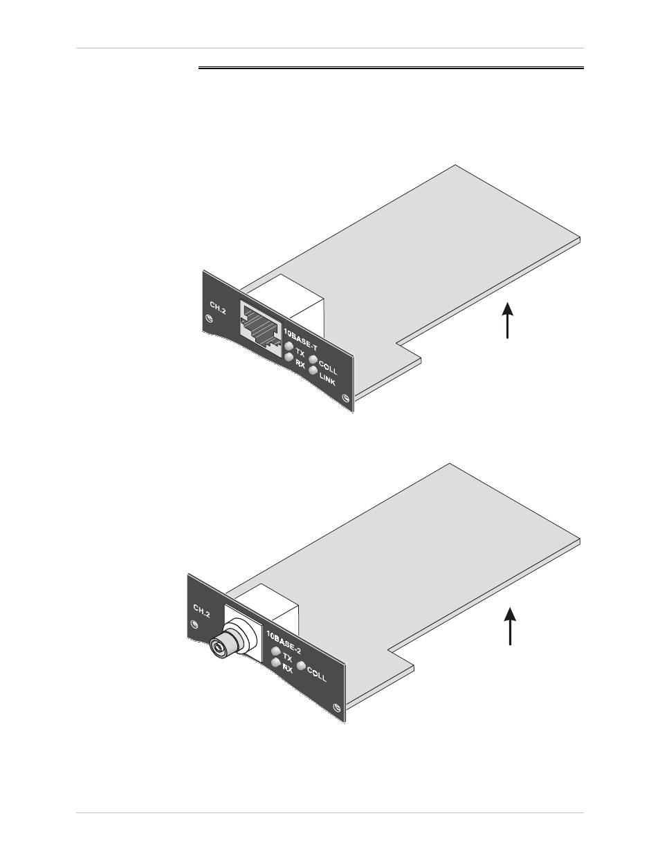
Figure C-4 and Figure C-5 show the Ethernet bridge rear panel components
for the 10BaseT and the 10Base2 versions, respectively. Figure C-6 shows
the location of the LED and the DIP switch.
View A
Figure C-4 IR-ETH Module Layout (10BaseT Option)
View A
Figure C-5 IR-ETH Module Layout (10Base2 Option)