Open the hcd-e1 case, Reinstall the hcd-e1 cover – RAD Data comm HCD-E1 User Manual
Page 49
HCD-E1 Installation & Operation Manual
Chapter 2 - Installation and Setup
11/12/00 10:36
Installation and Setup
2-3
Jumper C/R
Central
Unit
Remote
Unit
JP
4
R
J10
/C
C
R
C
R
FGND/GND ON
OFF
JP
8
ON
OFF
Not
Connected
Connected
FGND/GND
ON
S
P
ARE
P
A
SSW
D
DE
F
S
P
D
B
IN
IT
S1
Sublink
Interface Board
Data Channel 2
Interface Board
RJ-45
Connector
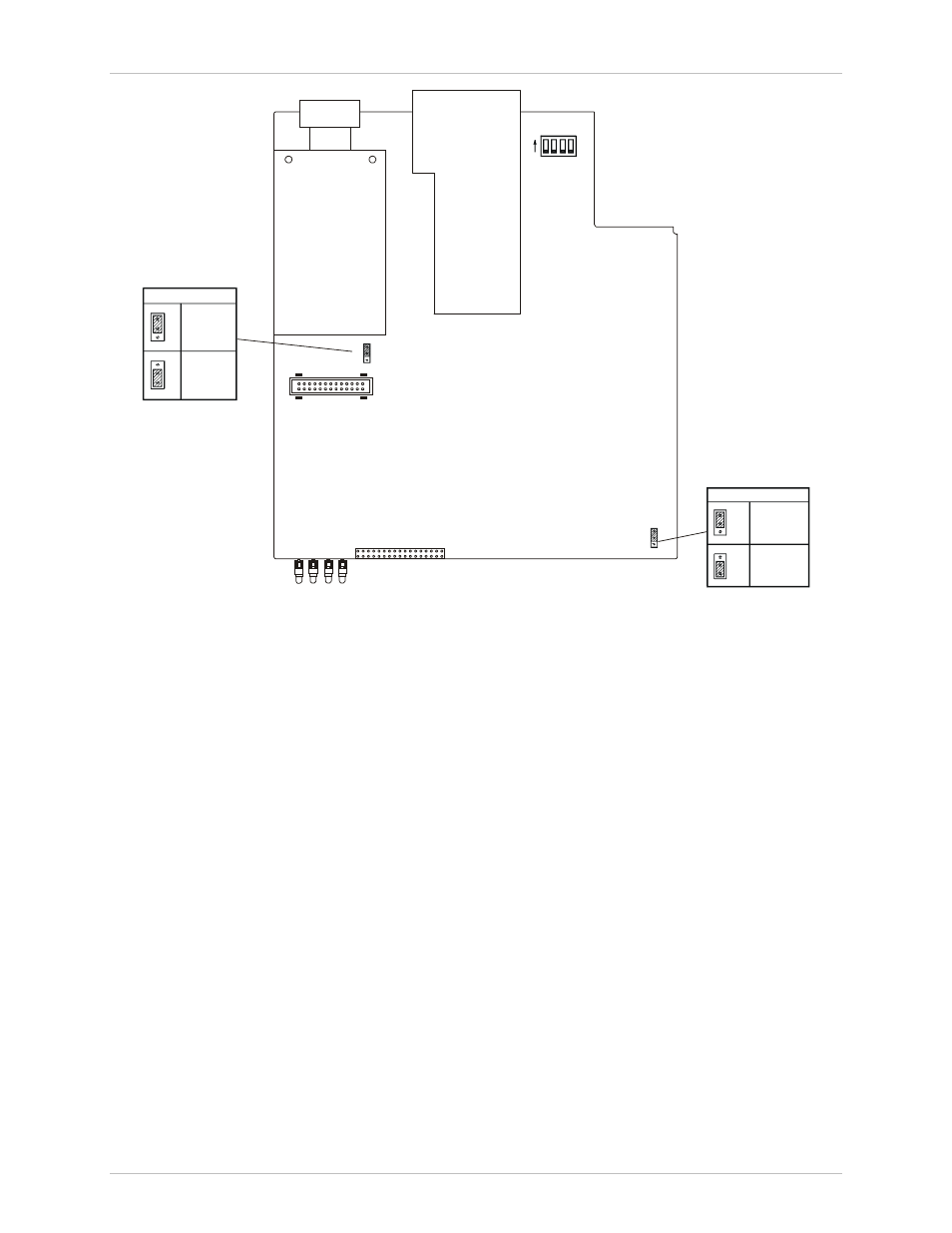
Figure 2-1 HCD-E1 - Identification of Boards, Jumpers and Switches
The Main Board contains the common signal processing circuits, the
interfaces to the main link (HDSL) and the Data Channel 1 interface. A DIP
switch unit (S1) and two jumpers (JP4 and JP8) are provided for user settings.
The board contains additional jumpers which are factory-set and should not
be changed by the user.
The Data Channel 2 Interface Board
provides the connections of data
channel 2. The board does not have any user-set jumpers or switches
(except for the Ethernet board, see Appendix C and Appendix D).
The E1 Sublink Interface Board provides the E1 connections and contains
several user-set jumpers.
To set the internal jumpers and switches, you must do the following in this
order:
•
Open the HCD-E1 case
•
Set the Main Board Jumpers and Switch, referring to Figure 2-1.
•
Remove the E1 Sublink Internal Board, if it is necessary to modify its
settings.
•
Identify jumper and switch locations and settings on the Sublink Interface
Board (referring to Figure 2-4) and change settings as required.
•
Reinstall the E1 Sublink Interface Board, if it has been removed.
•
Reinstall the HCD-E1 cover.