RAD Data comm HCD-E1 User Manual
Page 205
HCD-E1 Installation & Operation Manual
Appendix E - IR-IP Interface Module
Physical Descriptionr
E-3
IR-IP LEDs
IR-IP contains three LEDs, which indicate the module activity. Table E-1
lists the LEDs functions.
Table E-1 IR-IP LEDs Functions
Name
Type
Function
INT
Green LED
ON when IR-IP is powered up.
ACT
Yellow LED
Blinks when there is transmit/receive activity on the
Ethernet link.
ERR
Red LED
During regular operation, turns on when a buffer
overflow occurs.
During power-up, provides additional indications,
described below.
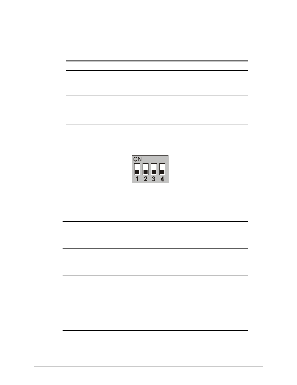
IR-IP DIP Switch
IR-IP interface module contains a four-section DIP switch, as seen in
Figure E-3. Table E-2 lists the DIP switch functions.
Figure E-3 IR-IP DIP Switch
Table E-2 IR-IP DIP Switch Functions
No
Function
Values
1
Enables IR-IP to learn its IP
ON
– IP address learning is enabled
OFF
– IP address learning is disabled
Default – OFF
2
Selects the WAN protocol
ON
– PPP protocol
OFF
– Frame Relay protocol
Default – OFF
3
Selects the LAN mode
ON
– Full duplex operation
OFF
– Half duplex operation
Default – OFF
4
Controls the remote WAN test
loopback, which returns packets
received from the WAN back
toward the WAN
ON
– The test loop is activated
OFF
– The test loop is disabled
Default – OFF