RAD Data comm HCD-E1 User Manual
Page 51
HCD-E1 Installation & Operation Manual
Chapter 2 - Installation and Setup
11/12/00 10:36
Installation and Setup
2-5
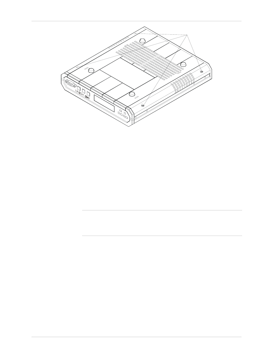
Cover Screws
(4 Places)
Cover Screws
(4 Places)
Figure 2-2 Identification of Cover Screws
Setting the Main Board Internal Jumpers and Switches
The internal jumpers and switches located on the HCD-E1 main board are
identified in Figure 2-1. The functions of jumpers and switches are described
below.
Switch S1
DIP switch S1 allows you to enforce the default password and node number
(section 4) or reload the desired group of default parameters (sections 2 and
3). Any changes in switch section positions must be performed on a unit not
connected to power.
Note
If you want to change the hardware configuration of your HCD-E1 (for
example, remove an E1 sublink or one of the data channels from the unit),
you will have to reload its database with default parameters (see below and
the DB INIT command in Chapter 4).
•
Switch section 1 –
not used in this unit and is reserved as spare.
•
Switch section 2 – DB INIT
. This section selects the source of the
database configuration parameters:
ON
HCD-E1 uses the default parameters stored in its
EPROM for reloading of the database.
OFF
HCD-E1 uses the parameters stored in the database.
HCD-E1 is delivered with the database loaded with the default
parameters. If needed, you can move the switch to the ON position
again, to reload the database and restart HCD-E1 with the default
parameters.
HCD-E1 is shipped with section 2 set at OFF
.