System timing – RAD Data comm HCD-E1 User Manual
Page 30
Chapter 1 - Introduction
HCD-E1
Installation & Operation Manual
1-12
Functional Description
01/01/01 08:07
System Timing
HCD-E1 offers selectable timing options, which enable the distribution of
timing over the HDSL system, from the central office to the remote end. The
use of stuffing on the HDSL subsystem ensures that the E1 signal and the
data rate provided to the customer equipment by the remote unit are
locked to the timing of the E1 signal and data rate received by the central
unit.
HCD-E1 Configured as Central Unit (LTU)
The HCD-E1 unit configured as LTU has two timing modes: external timing
and internal timing.
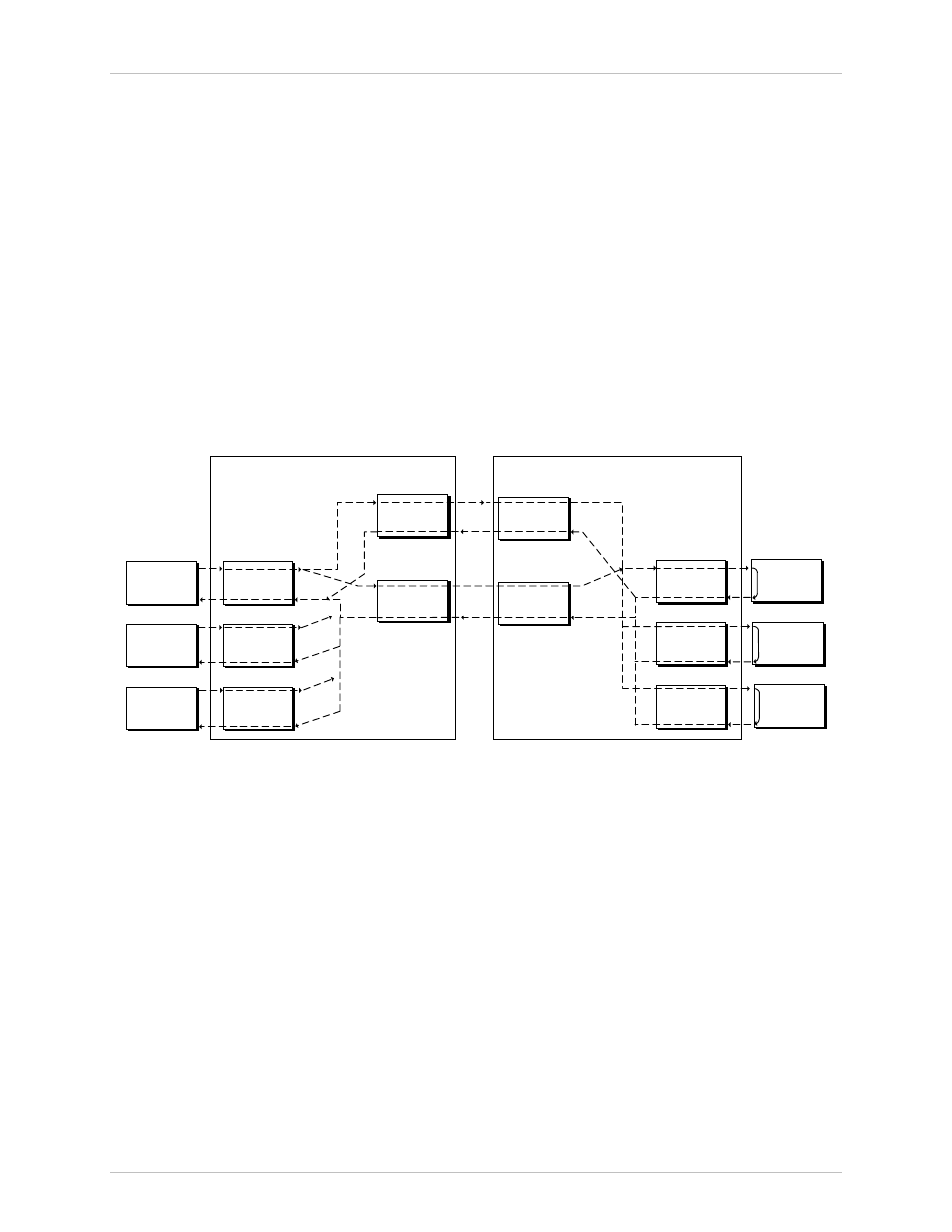
With external timing, the HCD-E1 system timing is locked to the clock
signals recovered from the incoming clock or to external clock signals
(derived from one of the synchronous data channels or from the E1 sublink).
Figure 1-5 shows the flow of timing signals through the HCD-E1 system in
the external timing mode.
NETWORK
SIDE
E1
INTERFACE
DATA
EQUIPMENT
DATA
CHANNEL 2
INTERFACE
DATA
EQUIPMENT
DATA
CHANNEL 1
INTERFACE
E1
INTERFACE
CUSTOMER
SIDE (DTE)
DATA
CHANNEL 2
INTERFACE
DATA
EQUIPMENT
DATA
CHANNEL 1
INTERFACE
DATA
EQUIPMENT
HDSL LINE B
INTERFACE
HDSL LINE
INTERFACE
HDSL LINE B
INTERFACE
HDSL LINE A
INTERFACE
TIMING
SOURCE
CENTRAL HCD-E1
HDSL
LINE B
HDSL
LINE A
REMOTE HCD-E1
LOOPBACK
TIMING
OR
OR
Figure 1-5 Flow of Timing Signals through HCD-E1 System in the External Timing Mode
With internal timing, the HCD-E1 system timing is determined by the clock
signal generated by an internal crystal oscillator. Figure 1-6 shows the flow of
timing signals through the HCD-E1 system in the internal timing mode.