Figure 5-4 lp r sl loopback – RAD Data comm HCD-E1 User Manual
Page 163
HCD-E1 Installation & Operation Manual
Chapter 5 - Troubleshooting and Diagnostics
01/01/01 08:15
Diagnostic Tests
5-23
LP L SL
This local loopback towards the E1 sublink of the local HCD-E1 is performed
by connecting the E1 sublink input signal (input to HCD-E1) to the output of
the sublink from HCD-E1, as shown in Figure 5-3. The test signal is provided
by the equipment connected to the E1 sublink of the local HCD-E1, which
must receive its own transmission without errors while the loopback is
activated.
This test fully checks the connections to the equipment connected to the E1
sublink of the local HCD-E1. During the loopback, the local HCD-E1
continues sending data from the DTE connected to its E1 sublink, over the
HDSL link.
Figure 5-3 LP L SL Loopback
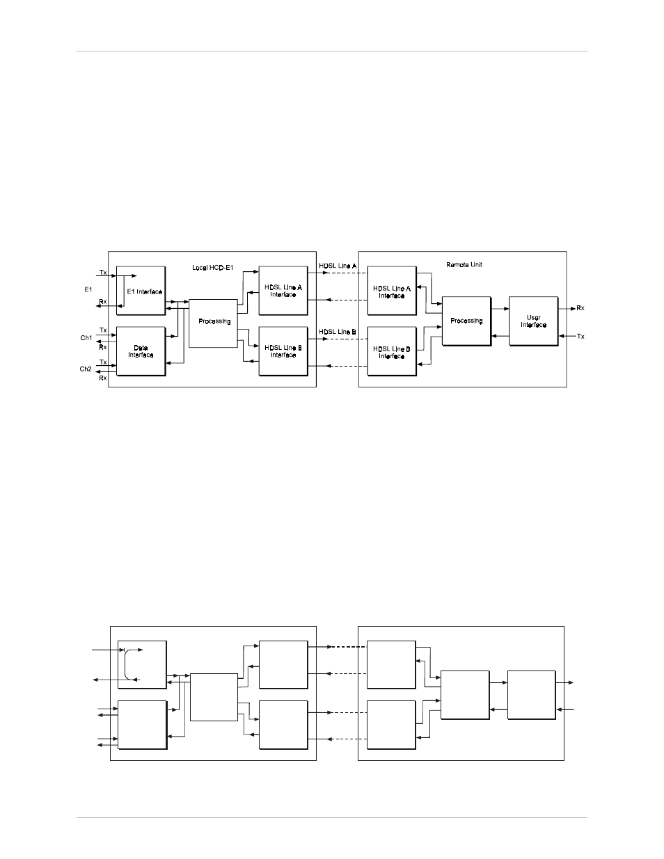
LP R SL
This remote loopback towards the DTE connected to the E1 sublink of the
remote HCD-E1 is performed by connecting the sublink transmit signal
(output from HCD-E1) to the sublink receive path (input from HCD-E1)
within the sublink line interface circuits, as shown in Figure 5-4. The test
signal is provided by the equipment connected to the E1 sublink of the
remote HCD-E1, which must receive its own transmission without errors
while the loopback is activated.
This test checks the connections to the equipment connected to the E1
sublink of the remote HCD-E1, all the circuits of the local and remote
HCD-E1, and the transmission path connecting the two units.
Local HCD-E1
Remote Unit
E1 Interface
Data
Interface
HDSL Line A
Interface
HDSL Line A
HDSL Line B
Processing
HDSL Line A
Interface
Processing
User
Interface
HDSL Line B
Interface
HDSL Line B
Interface
E1
Tx
Tx
Tx
Tx
Rx
Ch2
Ch1
Rx
Rx
Rx
Figure 5-4 LP R SL Loopback