Operating loopbacks from the front panel – RAD Data comm HCD-E1 User Manual
Page 167
HCD-E1 Installation & Operation Manual
Chapter 5 - Troubleshooting and Diagnostics
01/01/01 08:15
Diagnostic Tests
5-27
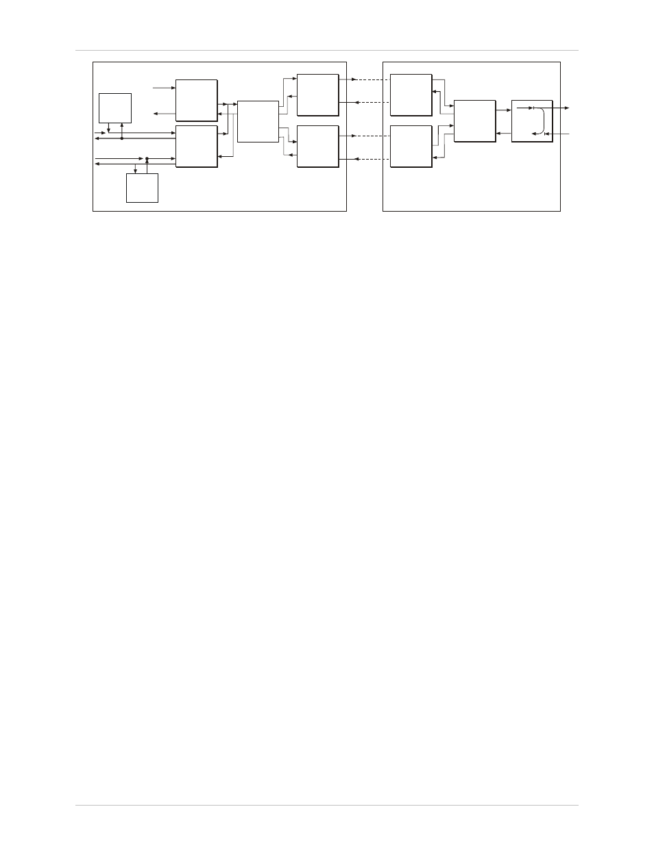
CH2
CH1
LOCAL HCD-E1
REMOTE UNIT
E1 Interface
Data
Interface
HDSL Line A
Interface
HDSL Line A
HDSL Line B
Processing
HDSL Line A
Interface
Processing
Data
Interface
HDSL Line B
Interface
HDSL Line B
Interface
E1
Tx
Tx
Tx
Tx
Rx
Rx
Rx
Rx
BERT
BERT
Figure 5-10 LP R R CH 1 Loopback + LP BERT CH 1
During the test, the local data channel is disconnected, the DSR line is off;
an internal pattern generator connects a user-selected test sequence to the
transmit input of the local data channel interface. To calibrate the system,
you can inject errors at a selectable rate.
The receive output is connected to a pattern evaluator. The evaluator
compares the received and transmitted patterns and detects errors. The test
results are presented as follows:
•
On the supervision terminal, detailed full data is displayed, including
information on factors such as the number of seconds during which
HCD-E1 lost frame synchronization (see the DSP BERT command in
Chapter 4).
•
On the LCD, the result appears as GOOD (no errors) or BAD (at least
one error has been detected during the BER measurement interval). For
more details, see “Operating BERT from the Front Panel” below.
Operating
Loopbacks from
the Front Panel
Before starting the execution of a test, pay attention to the following points:
• At any time, you can connect only one loopback on the E1 sublink, and
one on each channel.
• If a loopback is already connected, the TST indicator lights. If you try to
connect a loopback while another loopback of the same type is already
connected, HCD-E1 displays an error message.