RAD Data comm HCD-E1 User Manual
Page 196
Appendix C - IR-ETH Interface Module
HCD-E1 Installation & Operation Manual
C-4
Installation and Operation
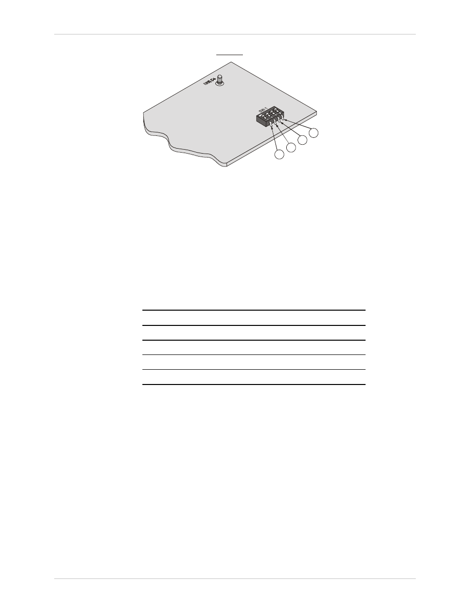
1
2
3
4
View A
Figure C-6 IR-ETH Module (View A)
LAN Installation
The Ethernet with UTP (10BaseT) connectors is designated as a Station. For
10BaseT installation, either a straight cable or a cross-cable may be required.
Use a cross-cable when connecting to a port that does not implement the
crossover function internally. Otherwise, use a straight cable. (Hubs usually
do implement the crossover function internally while network interface cards
and other devices do not).
Table C-1 lists pinout of the IR-Ethernet RJ-45 connector.
Table C-1 RJ-45 Pinout
Pin
Name
Function
1
TD (+)
Transmit data positive
2
TD (-)
Transmit data negative
3
RD (+)
Receive data positive
6
RD (-)
Receive data negative
Switch Settings
Table C-2 describes functions and default settings of the DIP switch SW-1
sections. Function of section 1 is software-controlled, either from the
supervision terminal (DEF CH command), or from the front panel
(CHANNEL PRM). Its hardware switch is permanently set to OFF and is not
allowed for manual setting. Sections 2 and 3 are set in accordance with
Table C-2.
The DIP switch is on the reverse side of the Ethernet bridge. To change the
switch settings, you must undo three screws on the board and detach it from
the main unit.