4 hdi08 block diagram, Hdi08 block diagram -4, Table 6-2 – Freescale Semiconductor DSP56366 User Manual
Page 98: Strobe signals support signals -4, Table 6-3, Host request support signals -4
HDI08 Block Diagram
DSP56366 24-Bit Digital Signal Processor User Manual, Rev. 4
6-4
Freescale Semiconductor
6.4
HDI08 Block Diagram
shows the HDI08 registers. The top row of registers (HCR, HSR, HDDR, HDR, HBAR, HPCR,
HOTX, HORX) can be accessed the DSP core. The bottom row of registers (ISR, ICR, CVR, IVR,
RXH:RXM:RXL and TXH:TXM:TXL) can be accessed by the host processor.
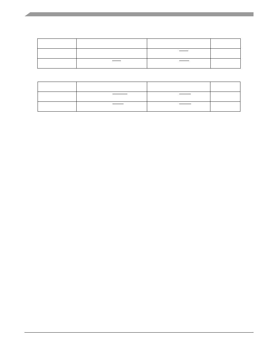
Table 6-2 Strobe Signals Support signals
HDI08 Port Pin
Single strobe bus
Dual strobe bus
GPIO Mode
HRW/HRD
HRW
HRD/HRD
PB11
HDS/HWR
HDS/HDS
HWR/HWR
PB12
Table 6-3 Host request support signals
HDI08 Port Pin
Vector required
No vector required
GPIO Mode
HOREQ/HTRQ
HOREQ/HOREQ
HTRQ/HTRQ
PB14
HACK/HRRQ
HACK/HACK
HRRQ/HRRQ
PB15