1 saicr serial output flag 0 (of0) - bit 0, 2 saicr serial output flag 1 (of1) - bit 1, 3 saicr serial output flag 2 (of2) - bit 2 – Freescale Semiconductor DSP56366 User Manual
Page 182: 4 saicr reserved bits - bits 3-5, 9-23, 5 saicr synchronous mode selection (syn) - bit 6, Saicr serial output flag 0 (of0) - bit 0 -32, Saicr serial output flag 1 (of1) - bit 1 -32, Saicr serial output flag 2 (of2) - bit 2 -32, Saicr reserved bits - bits 3-5, 9-23 -32, Saicr synchronous mode selection (syn) - bit 6 -32
ESAI Programming Model
DSP56366 24-Bit Digital Signal Processor User Manual, Rev. 4
8-32
Freescale Semiconductor
Hardware and software reset clear all the bits in the SAICR register.
8.3.5.1
SAICR Serial Output Flag 0 (OF0) - Bit 0
The Serial Output Flag 0 (OF0) is a data bit used to hold data to be send to the OF0 pin. When the ESAI
is in the synchronous clock mode (SYN=1), the SCKR pin is configured as the ESAI flag 0. If the receiver
serial clock direction bit (RCKD) is set, the SCKR pin is the output flag OF0, and data present in the OF0
bit is written to the OF0 pin at the beginning of the frame in normal mode or at the beginning of the next
time slot in network mode.
8.3.5.2
SAICR Serial Output Flag 1 (OF1) - Bit 1
The Serial Output Flag 1 (OF1) is a data bit used to hold data to be send to the OF1 pin. When the ESAI
is in the synchronous clock mode (SYN=1), the FSR pin is configured as the ESAI flag 1. If the receiver
frame sync direction bit (RFSD) is set and the TEBE bit is cleared, the FSR pin is the output flag OF1, and
data present in the OF1 bit is written to the OF1 pin at the beginning of the frame in normal mode or at the
beginning of the next time slot in network mode.
8.3.5.3
SAICR Serial Output Flag 2 (OF2) - Bit 2
The Serial Output Flag 2 (OF2) is a data bit used to hold data to be send to the OF2 pin. When the ESAI
is in the synchronous clock mode (SYN=1), the HCKR pin is configured as the ESAI flag 2. If the receiver
high frequency clock direction bit (RHCKD) is set, the HCKR pin is the output flag OF2, and data present
in the OF2 bit is written to the OF2 pin at the beginning of the frame in normal mode or at the beginning
of the next time slot in network mode.
8.3.5.4
SAICR Reserved Bits - Bits 3-5, 9-23
These bits are reserved. They read as zero, and they should be written with zero for future compatibility.
8.3.5.5
SAICR Synchronous Mode Selection (SYN) - Bit 6
The Synchronous Mode Selection (SYN) bit controls whether the receiver and transmitter sections of the
ESAI operate synchronously or asynchronously with respect to each other (see
). When SYN
is cleared, the asynchronous mode is chosen and independent clock and frame sync signals are used for
11
10
9
8
7
6
5
4
3
2
1
0
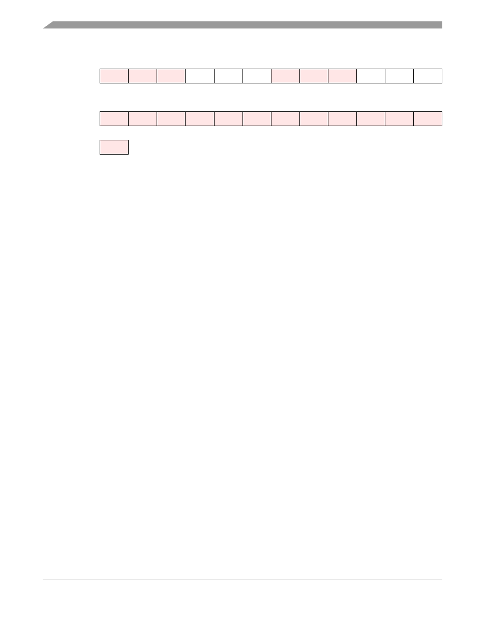
X:$FFFFB4
ALC
TEBE
SYN
OF2
OF1
OF0
23
22
21
20
19
18
17
16
15
14
13
12
Reserved bit - read as zero; should be written with zero for future compatibility.
Figure 8-10 SAICR Register