1 saisr serial input flag 0 (if0) - bit 0, 2 saisr serial input flag 1 (if1) - bit 1, 3 saisr serial input flag 2 (if2) - bit 2 – Freescale Semiconductor DSP56366 User Manual
Page 185: 4 saisr reserved bits - bits 3-5, 11-12, 18-23, 5 saisr receive frame sync flag (rfs) - bit 6, Saisr serial input flag 0 (if0) - bit 0 -35, Saisr serial input flag 1 (if1) - bit 1 -35, Saisr serial input flag 2 (if2) - bit 2 -35, Saisr reserved bits - bits 3-5, 11-12, 18-23 -35, Saisr receive frame sync flag (rfs) - bit 6 -35
ESAI Programming Model
DSP56366 24-Bit Digital Signal Processor User Manual, Rev. 4
Freescale Semiconductor
8-35
8.3.6.1
SAISR Serial Input Flag 0 (IF0) - Bit 0
The IF0 bit is enabled only when the SCKR pin is defined as ESAI in the Port Control Register, SYN=1
and RCKD=0, indicating that SCKR is an input flag and the synchronous mode is selected. Data present
on the SCKR pin is latched during reception of the first received data bit after frame sync is detected. The
IF0 bit is updated with this data when the receiver shift registers are transferred into the receiver data
registers. IF0 reads as a zero when it is not enabled. Hardware, software, ESAI individual, and STOP reset
clear IF0.
8.3.6.2
SAISR Serial Input Flag 1 (IF1) - Bit 1
The IF1 bit is enabled only when the FSR pin is defined as ESAI in the Port Control Register, SYN =1,
RFSD=0 and TEBE=0, indicating that FSR is an input flag and the synchronous mode is selected. Data
present on the FSR pin is latched during reception of the first received data bit after frame sync is detected.
The IF1 bit is updated with this data when the receiver shift registers are transferred into the receiver data
registers. IF1 reads as a zero when it is not enabled. Hardware, software, ESAI individual, and STOP reset
clear IF1.
8.3.6.3
SAISR Serial Input Flag 2 (IF2) - Bit 2
The IF2 bit is enabled only when the HCKR pin is defined as ESAI in the Port Control Register, SYN=1
and RHCKD=0, indicating that HCKR is an input flag and the synchronous mode is selected. Data present
on the HCKR pin is latched during reception of the first received data bit after frame sync is detected. The
IF2 bit is updated with this data when the receive shift registers are transferred into the receiver data
registers. IF2 reads as a zero when it is not enabled. Hardware, software, ESAI individual, and STOP reset
clear IF2.
8.3.6.4
SAISR Reserved Bits - Bits 3-5, 11-12, 18-23
These bits are reserved for future use. They read as zero.
8.3.6.5
SAISR Receive Frame Sync Flag (RFS) - Bit 6
When set, RFS indicates that a receive frame sync occurred during reception of the words in the receiver
data registers. This indicates that the data words are from the first slot in the frame. When RFS is clear and
11
10
9
8
7
6
5
4
3
2
1
0
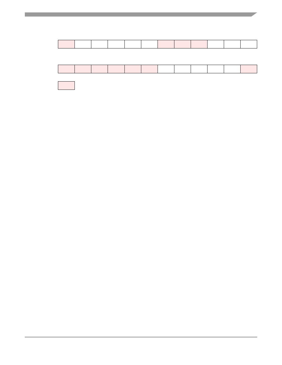
X:$FFFFB3
RODF
REDF
RDF
ROE
RFS
IF2
IF1
IF0
23
22
21
20
19
18
17
16
15
14
13
12
TODE
TEDE
TDE
TUE
TFS
Reserved bit - read as zero; should be written with zero for future compatibility.
Figure 8-12 SAISR Register