5 external memory expansion port (port a), 1 external address bus, 2 external data bus – Freescale Semiconductor DSP56366 User Manual
Page 39: 3 external bus control, External memory expansion port (port a) -5, External address bus -5, External data bus -5, External bus control -5, Table 2-5, External address bus signals -5
External Memory Expansion Port (Port A)
DSP56366 24-Bit Digital Signal Processor User Manual, Rev. 4
Freescale Semiconductor
2-5
2.5
External Memory Expansion Port (Port A)
When the DSP56364 enters a low-power standby mode (stop or wait), it releases bus mastership and
tri-states the relevant port A signals: A0 – A17, D0 – D23, AA0/RAS0 – AA2/RAS2, RD, WR, BB, CAS.
2.5.1
External Address Bus
2.5.2
External Data Bus
2.5.3
External Bus Control
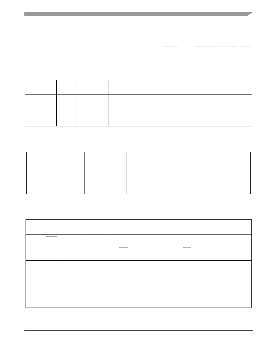
Table 2-5 External Address Bus Signals
Signal Name
Type
State during
Reset
Signal Description
A0–A17
Output
Tri-stated
Address Bus — When the DSP is the bus master, A0 – A17 are active-high
outputs that specify the address for external program and data memory
accesses. Otherwise, the signals are tri-stated. To minimize power dissipation,
A0 – A17 do not change state when external memory spaces are not being
accessed.
Table 2-6 External Data Bus Signals
Signal Name
Type
State during Reset
Signal Description
D0–D23
Input/Output
Tri-stated
Data Bus — When the DSP is the bus master,
D0 – D23 are active-high, bidirectional input/outputs that provide the
bidirectional data bus for external program and data memory
accesses. Otherwise,
D0 – D23 are tri-stated.
Table 2-7 External Bus Control Signals
Signal Name
Type
State during
Reset
Signal Description
AA0–AA2/RAS0
– RAS2
Output
Tri-stated
Address Attribute or Row Address Strobe — When defined as AA, these
signals can be used as chip selects or additional address lines. When defined
as RAS, these signals can be used as RAS for DRAM interface. These
signals are tri-statable outputs with programmable polarity.
CAS
Output
Tri-stated
Column Address Strobe — When the DSP is the bus master, CAS is an
active-low output used by DRAM to strobe the column address. Otherwise, if
the bus mastership enable (BME) bit in the DRAM control register is cleared,
the signal is tri-stated.
RD
Output
Tri-stated
Read Enable — When the DSP is the bus master, RD is an active-low output
that is asserted to read external memory on the data bus (D0-D23).
Otherwise, RD is tri-stated.