1 prescaler counter, 2 timer prescaler load register (tplr), 1 tplr prescaler preload value pl[20:0] bits 20-0 – Freescale Semiconductor DSP56366 User Manual
Page 235: 2 tplr prescaler source ps[1:0] bits 22-21, Prescaler counter -5, Timer prescaler load register (tplr) -5, Tplr prescaler preload value pl[20:0] bits 20–0 -5, Tplr prescaler source ps[1:0] bits 22-21 -5, Figure 11-4
Timer/Event Counter Programming Model
DSP56366 24-Bit Digital Signal Processor User Manual, Rev. 4
Freescale Semiconductor
11-5
11.3.1
Prescaler Counter
The prescaler counter is a 21-bit counter that is decremented on the rising edge of the prescaler input clock.
The counter is enabled when at least one of the three timers is enabled (i.e., one or more of the timer enable
(TE) bits are set) and is using the prescaler output as its source (i.e., one or more of the PCE bits are set).
11.3.2
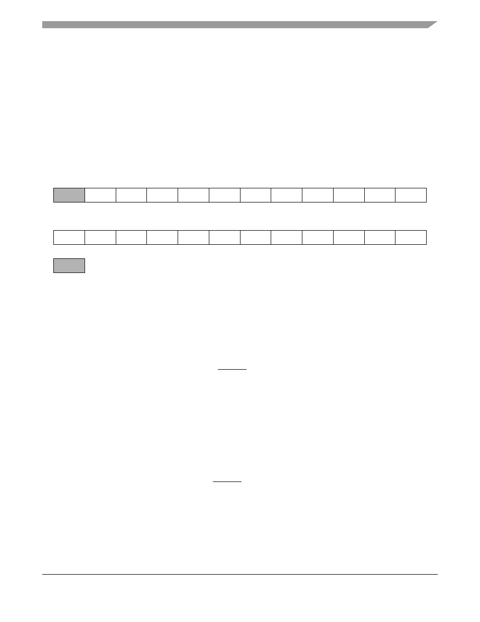
Timer Prescaler Load Register (TPLR)
The TPLR is a 24-bit read/write register that controls the prescaler divide factor (i.e., the number that the
prescaler counter will load and begin counting from) and the source for the prescaler input clock. See
.
11.3.2.1
TPLR Prescaler Preload Value PL[20:0] Bits 20–0
These 21 bits contain the prescaler preload value. This value is loaded into the prescaler counter when the
counter value reaches zero or the counter switches state from disabled to enabled.
If PL[20:0] = N, then the prescaler counts N + 1 source clock cycles before generating a prescaler clock
pulse. Therefore, the prescaler divide factor = (preload value) + 1.
The PL[20:0] bits are cleared by the hardware RESET signal or the software RESET instruction.
11.3.2.2
TPLR Prescaler Source PS[1:0] Bits 22-21
The two prescaler source (PS) bits control the source of the prescaler clock. Table 9-1 summarizes PS bit
functionality. The prescaler’s use of the TIO0 signal is not affected by the TCSR settings of timer 0.
If the prescaler source clock is external, the prescaler counter is incremented by signal transitions on the
TIO0 signal. The external clock is internally synchronized to the internal clock. The external clock
frequency must be lower than the DSP56366 internal operating frequency divided by 4 (CLK/4).
The PS[1:0] bits are cleared by the hardware RESET signal or the software RESET instruction.
NOTE
To ensure proper operation, change the PS[1:0] bits only when the prescaler
counter is disabled. Disable the prescaler counter by clearing the TE bit in
the TCSR of each of three timers.
23
22
21
20
19
18
17
16
15
14
13
12
PS1
PS0
PL20
PL19
PL18
PL17
PL16
PL15
PL14
PL13
PL12
11
10
9
8
7
6
5
4
3
2
1
0
PL11
PL10
PL9
PL8
PL7
PL6
PL5
PL4
PL3
PL2
PL1
PL0
— reserved, read as 0, should be written with 0 for future compatibility
Figure 11-4 Timer Prescaler Load Register (TPLR)