3 timer/event counter programming model, Timer/event counter programming model -3, Figure 11-2 – Freescale Semiconductor DSP56366 User Manual
Page 233: Timer block diagram -3
Timer/Event Counter Programming Model
DSP56366 24-Bit Digital Signal Processor User Manual, Rev. 4
Freescale Semiconductor
11-3
11.3
Timer/Event Counter Programming Model
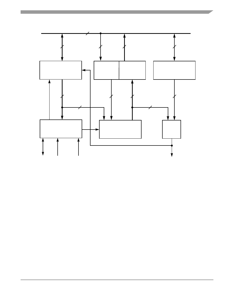
The DSP56366 views each timer as a memory-mapped peripheral with four registers occupying four 24-bit
words in the X data memory space. Either standard polled or interrupt programming techniques can be
used to service the timers. The timer programming model is shown in
.
Figure 11-2 Timer Block Diagram
GDB
Control/Status
Register
TCSR
Counter
Timer interrupt/
Timer Control
CLK/2
TIO
Compare
Register
TCPR
=
24
24
DMA request
Logic
Load
Register
Count
Register
TLR
prescaler CLK
TCR
24
24
9
2
24
24
24
24
24
(Timer 0
only)
AA0676